TECHNICAL TABLES
Just Find Your Technical Answers Below:
| Designation of Diameter | O/D | Nominal Wall Thickness | ||||||||||||||||||
| DIA | SCH.5S | SCH.5 | SCH 10S | SCH.10 | SCH.20S | SCH.30 | SCH.40S | SCH.40 | SCH 60 | |||||||||||
| (A) | (B) | Meter MM |
Wall Thk |
Weight Kg/Mtr | Wall Thk |
Weight Kg/Mtr | Wall Thk |
Weight Kg/Mtr | Wall Thk |
Weight Kg/Mtr | Wall Thk |
Weight Kg/Mtr | Wall Thk |
Weight Kg/Mtr | Wall Thk |
Weight Kg/Mtr | Wall Thk |
Weight Kg/Mtr | Wall Thk |
Weight Kg/Mtr |
| 6 | 1/8 | 10.3 | 1 | 0.23 | 1.2 | 0.27 | 1.5 | 0.33 | 1.73 | 0.37 | ||||||||||
| 8 | 1/4 | 13.7 | 1.2 | 0.37 | 1.65 | 0.49 | 2 | 0.58 | 2.24 | 0.64 | ||||||||||
| 10 | 3/8 | 17.2 | 1.2 | 0.47 | 1.65 | 0.63 | 2 | 0.74 | 2.31 | 0.87 | ||||||||||
| 15 | 1/2 | 21.3 | 1.65 | 0.01 | 1.65 | 0.81 | 2.11 | 1.02 | 2.11 | 1.02 | 2.5 | 1.15 | 2.77 | 1.29 | ||||||
| 20 | 3/4 | 26.7 | 1.65 | 1.03 | 1.65 | 1.03 | 2.11 | 1.3 | 2.11 | 1.3 | 2.5 | 1.49 | 2.87 | 1.71 | ||||||
| 25 | 1 | 33.4 | 1.65 | 1.31 | 1.65 | 1.31 | 2.77 | 2.13 | 2.77 | 2.13 | 3 | 2.24 | 3.38 | 2.54 | ||||||
| 32 | 11/4 | 24.2 | 1.65 | 1.67 | 1.65 | 1.67 | 2.77 | 2.73 | 2.77 | 2.73 | 3 | 2.9 | 3.56 | 3.44 | ||||||
| 40 | 11/2 | 48.3 | 1.65 | 1.93 | 1.65 | 1.93 | 2.77 | 3.16 | 2.77 | 3.16 | 3 | 3.35 | 3.68 | 4.11 | ||||||
| 50 | 2 | 60.3 | 1.65 | 1.93 | 1.65 | 2.42 | 2.77 | 3.99 | 2.77 | 3.99 | 3.5 | 4.9 | 3.91 | 5.52 | ||||||
| 65 | 21/2 | 73 | 2.11 | 3.75 | 2.11 | 3.75 | 3.05 | 5.34 | 3.05 | 5.34 | 3.5 | 6 | 5.16 | 8.77 | ||||||
| 80 | 3 | 88.9 | 2.11 | 4.59 | 2.11 | 4.59 | 3.05 | 6.56 | 3.05 | 6.56 | 4 | 8.37 | 5.49 | 11.47 | ||||||
| 90 | 31/2 | 101.6 | 2.11 | 5.25 | 2.11 | 5.25 | 3.05 | 7.53 | 3.05 | 7.53 | 4 | 9.62 | 5.74 | 13.78 | ||||||
| 100 | 4 | 114.3 | 2.11 | 5.93 | 2.11 | 5.93 | 3.05 | 8.5 | 3.05 | 8.5 | 4.5 | 12.18 | 6.02 | 6.32 | ||||||
| 125 | 5 | 141.3 | 2.77 | 9.61 | 2.77 | 9.61 | 3.4 | 11.74 | 3.43 | 11.74 | 5 | 16.8 | 6.55 | 2210 | ||||||
| 150 | 6 | 168.3 | 2.77 | 11.47 | 2.77 | 11.47 | 3.4 | 14.04 | 3.43 | 14.04 | 5.5 | 22.08 | 7.11 | 28.69 | ||||||
| 200 | 8 | 219.1 | 2.77 | 15 | 2.77 | 15 | 3.76 | 20.77 | 3.76 | 20.27 | 6.35 | 33.82 | 7.04 | 37.38 | 8.18 | 43.2 | 10.81 | 53.9 | ||
| 250 | 10 | 273.1 | 3.4 | 22.95 | 3.4 | 22.95 | 4.19 | 28.2 | 4.19 | 28.2 | 6.35 | 42.41 | 7.8 | 51.81 | 9.27 | 61.22 | 12.2 | 82.8 | ||
| 300 | 12 | 323.9 | 3.96 | 31.72 | 4.19 | 33.6 | 4.57 | 36.54 | 4.57 | 36.54 | 6.35 | 50.48 | 8.38 | 66.2 | 9.53 | 75.01 | 10.31 | 80.94 | 14.27 | 110.62 |
| 350 | 14 | 355.6 | 3.96 | 34.86 | 4.78 | 41.99 | 6.35 | 55.53 | 7.92 | 68.95 | 9.53 | 82.58 | 9.53 | 82.58 | 11.13 | 96 | 15.06 | 128.42 | ||
| 400 | 16 | 406.4 | 4.19 | 42.2 | 4.78 | 48.07 | 6.35 | 63.61 | 7.92 | 79.03 | 9.53 | 94.7 | 9.53 | 94.7 | 12.7 | 125.2 | 16.66 | 162.59 | ||
| 450 | 18 | 457.2 | 4.19 | 47.46 | 4.78 | 54.15 | 6.35 | 71.69 | 7.92 | 89.1 | 11.13 | 124.32 | 9.53 | 106.83 | 14.27 | 158.27 | 19.05 | 209 | ||
| 500 | 2C | 508 | 4.78 | 60.23 | 5.54 | 69.7 | 6.35 | 79.76 | 9.53 | 118.93 | 12.7 | 157.51 | 9.53 | 118.9 | 15.06 | 185.89 | 2062 | 251.65 | ||
| 550 | 22 | 558.8 | 4.78 | 65.95 | 5.54 | 76.75 | 6.35 | 87.84 | 9.53 | 131.07 | 12.7 | 173.66 | 9.53 | 131.07 | 15.88 | 216.04 | 22.23 | 298.55 | ||
| 600 | 24 | 609.6 | 5.54 | 83.8 | 6.35 | 95.92 | 6.35 | 95.92 | 9.53 | 143.2 | 14.27 | 212.72 | 9.53 | 143.2 | 17.45 | 258.74 | 24.59 | 360.21 | ||
| 650 | 26 | 660.4 | 7.92 | 129.4 | 12.7 | 205.97 | 9.53 | 155.32 | ||||||||||||
| 700 | 28 | 711.2 | 7.92 | 139.47 | 12.7 | 222.13 | 15.88 | 276.48 | 9.53 | 167.44 | ||||||||||
| 750 | 3C | 762 | 6.35 | 120.15 | 7.92 | 149.55 | 7.92 | 149.55 | 12.7 | 238.28 | 15.88 | 296.68 | 9.53 | 179.56 | ||||||
| 800 | 32 | 812.8 | 7.92 | 159.62 | 12.7 | 254.44 | 15.88 | 316.88 | 9.53 | 191.69 | 17.48 | 348.11 | ||||||||
| 850 | 34 | 863.6 | 7.92 | 169.64 | 12.7 | 270.5 | 15.88 | 336.96 | 9.53 | 203.74 | 17.48 | 370.22 | ||||||||
| 900 | 36 | 914.4 | 7.92 | 179.77 | 12.7 | 286.75 | 15.88 | 357.28 | 9.53 | 215.93 | 19.05 | 427.09 | ||||||||
| Designation of Diameter | O/D | Nominal Wall Thickness | ||||||||||||||
| DIA | SCH 80 S | SCH 80 | SCH 100 | SCH 120 | SCH. 140 | SCH.160 | SCH.XXS | |||||||||
| (A) | (B) | Meter MM |
Wall Thk |
Weight Kg/Mtr | Wall Thk |
Weight Kg/Mtr | Wall Thk |
Weight Kg/Mtr | Wall Thk |
Weight Kg/Mtr | Wall Thk |
Weight Kg/Mtr | Wall Thk |
Weight Kg/Mtr | Wall Thk |
Weight Kg/Mtr |
| 6 | 1/8 | 10.3 | 2.41 | 0.47 | ||||||||||||
| 8 | 1/4 | 13.7 | 3.02 | 0.82 | ||||||||||||
| 10 | 3/8 | 17.2 | 3.2 | 1.12 | ||||||||||||
| 15 | 1/2 | 21.3 | 3.73 | 1.64 | 4.75 | 1.97 | 7.47 | 2.59 | ||||||||
| 20 | 3/4 | 26.7 | 3.91 | 2.93 | 5.54 | 2.93 | 7.82 | 3.69 | ||||||||
| 25 | 1 | 33.4 | 4.55 | 3.29 | 6.35 | 4.3 | 9.09 | 5.53 | ||||||||
| 32 | 11/4 | 24.2 | 4.85 | 4.53 | 6.35 | 5.69 | 9.7 | 7.88 | ||||||||
| 40 | 11/2 | 48.3 | 5.08 | 5.49 | 7.14 | 7.35 | 10.16 | 9.69 | ||||||||
| 50 | 2 | 60.3 | 5.54 | 7.6 | 8.71 | 11.26 | 11.07 | 13.65 | ||||||||
| 65 | 21/2 | 73 | 7.01 | 11.59 | 9.53 | 15.15 | 14.02 | 20.72 | ||||||||
| 80 | 3 | 88.9 | 7.62 | 15.51 | 11.13 | 21.67 | 15.24 | 28.11 | ||||||||
| 90 | 31/2 | 101.6 | 8.08 | 18.92 | 16.15 | 34.56 | ||||||||||
| 100 | 4 | 114.3 | 8.56 | 22.66 | 11.13 | 28.75 | 13.49 | 34.05 | 17.12 | 41.66 | ||||||
| 125 | 5 | 141.3 | 9.53 | 31.44 | 12.7 | 40.9 | 15.88 | 49.87 | 19.05 | 58.31 | ||||||
| 150 | 6 | 168.3 | 10.97 | 43.21 | 14.27 | 55.03 | 18.24 | 68.53 | 21.95 | 79.1 | ||||||
| 200 | 8 | 219.1 | 12.7 | 65.63 | 15.06 | 76.93 | 18.24 | 91.73 | 20.62 | 102.47 | 23.01 | 112.97 | 22.23 | 108 | ||
| 250 | 10 | 273.1 | 12.7 | 82.8 | 15.06 | 97.27 | 18.24 | 116.38 | 21.41 | 134.9 | 25.4 | 157.51 | 28.58 | 174.95 | 25.4 | 155.5 |
| 300 | 12 | 323.9 | 12.7 | 98.95 | 17.45 | 133.88 | 21.41 | 162.14 | 25.4 | 189.82 | 28.58 | 211.31 | 33.32 | 242.4 | 25.4 | 189.82 |
| 350 | 14 | 355.6 | 12.7 | 109.04 | 19.05 | 160.54 | 23.8 | 197.74 | 27.76 | 227.88 | 31.75 | 257.47 | 35.71 | 286.04 | ||
| 400 | 16 | 406.4 | 12.7 | 125.2 | 21.41 | 206.4 | 26.19 | 249.34 | 30.94 | 290.88 | 36.53 | 338.32 | 40.46 | 370.74 | ||
| 450 | 18 | 457.2 | 12.7 | 141.35 | 23.8 | 258.29 | 29.36 | 314.54 | 34.93 | 369.34 | 39.67 | 414.74 | 45.24 | 466.67 | ||
| 500 | 2C | 508 | 12.7 | 157.51 | 26.19 | 315.97 | 32.54 | 387.41 | 38.1 | 448.3 | 44.45 | 515.94 | 49.99 | 573.31 | ||
| 550 | 22 | 558.8 | 12.7 | 173.66 | 28.57 | 379.7 | 34.92 | 457.83 | 41.27 | 535.17 | 47.62 | 609.3 | 53.97 | 682.57 | ||
| 600 | 24 | 609.6 | 12.7 | 189.82 | 30.94 | 448.3 | 38.89 | 555.76 | 46.02 | 649.44 | 52.37 | 730.72 | 59.51 | 819.7 | ||
| 650 | 26 | 660.4 | 12.7 | 205.97 | (24.66D-t) t 1000 Wt/pam + formula Weight Stainless Steel Pipe OD (mm) - W.T. (mm) XW.T. (mm) X 0.02466 = Kg. per mtr. |
|||||||||||
| 700 | 28 | 711.2 | 12.7 | 222.13 | ||||||||||||
| 750 | 3C | 762 | 1270 | 238.28 | ||||||||||||
| 800 | 32 | 812.8 | 12.7 | 254.44 | ||||||||||||
| 850 | 34 | 863.6 | 12.7 | 270.5 | ||||||||||||
| 900 | 36 | 914.4 | 12.7 | 286.75 | ||||||||||||
| Dimension | 10SWg | 12SWg | 14SWg | 16SWg | 18SWg | 20SWg | 22SWg | |
| Size inches | OD in mm | 3.25mm Wt Kg/M | 2.64mm Wt Kg/M | 2.03mm Wt Kg/M | 1.62mm Wt Kg/M | 1.21mm Wt Kg/M | 0.91mm Wt Kg/M | 0.71mm Wt Kg/M |
| 3/8 | 9.52 | 0.549 | 0.447 | 0.405 | 0.341 | 0.268 | 0.193 | 0.165 |
| 1/2 | 12.7 | 0.768 | 0.654 | 0.542 | 0.451 | 0.350 | 0.264 | 0.213 |
| 3/4 | 19.05 | 1.285 | 1.068 | 0.864 | 0.710 | 0.544 | 0.407 | 0.320 |
| 1 | 25.4 | 1.801 | 1.482 | 1.187 | 0.969 | 0.738 | 0.549 | 0.432 |
| 1 1/4 | 31.75 | 2.801 | 1.482 | 1.187 | 0.969 | 0.738 | 0.549 | 0.432 |
| 1 1/2 | 38.1 | 2.834 | 2.309 | 1.832 | 1.487 | 1.126 | 0.820 | 0.654 |
| 1 3/4 | 45.00 | 3.408 | 2.722 | 2.191 | 1.775 | 1.341 | 0.834 | |
| 2 | 50.8 | 3.868 | 3.136 | 2.478 | 2.006 | 1.541 | 1.119 | 0.877 |
| 2 | 50.8 | 3.868 | 3.136 | 2.478 | 2.006 | 1.541 | 1-119 | 0.877 |
| 2 1/2 | 63.5 | 4.901 | 3.963 | 3.123 | 2.524 | 1.858 | - | - |
| 3 | 76.2 | 5.934 | 4.790 | 3.453 | 2.789 | 2.237 | - | - |
| 3 1/2 | 88.9 | 6.964 | 5.617 | 4.413 | 3.560 | 2.616 | - | - |
| 4 | 101.6 | 8.000 | 6.444 | 5.059 | 4.078 | 2.995 | - | - |
| 4 1/2 | 114.3 | 8.900 | 7.272 | 5.620 | 4.501 | 3.374 | - | - |
| 5 | 127-0 | 9.917 | 8.099 | 6.255 | 5.008 | 3.753 | - | - |
| 6 | 152.4 | 11.953 | 9.753 | 7.527 | 6.023 | 4.474 | - | - |
| Specification | Allowable Outside Diameter Variation in mm | Allowable Wall Thickness Variation | Exact Length Tolerance in mm | Testing | ||||
| Nominal Diameter | Over | Under | %Over | %Under | Over | Under | ||
| ASTM-A213 Seamless Boiler Superheater and Heat Exchanger Tubes |
Under 25.4 | .1016 | .1016 | +20 | -0 | 3.175 | 0 | Flattening Test |
| 25.4-38.1 incl | .1524 | .1524 | +22 | -0 | 3.175 | 0 | Tension Test | |
| 38.1-50.8 excl | .2032 | .2032 | +22 | -0 | 3.176 | 0 | Flare Test | |
| 50.8-63.5 excl | .254 | .254 | +2 | -0 | 4.46 | 0 | Hardness Test | |
| 63.5-76.2 excl | .3048 | .3048 | +22 | -0 | 4.76 | 0 | 100% Hydrostatic test | |
| 76.2-101.6 incl | .381 | .381 | +22 | -0 | 4.76 | 0 | Refer to ASTM A-450 | |
| ASTM-A249 Welded Boiler Superheater, Heat Exchanger And Condenser Tubes |
Under 25.4 | .1016 | .1016 | +10 | -10 | 3.175 | 0 | Tension Test |
| 25.4-38.1 incl | .1524 | .1524 | +10 | -10 | 3.175 | 0 | Flattening Test | |
| 38.1-50.8 Excl | .2032 | .2032 | +10 | -10 | 3.175 | 0 | Flange Test | |
| 50.0-63.5 excl | .254 | .254 | +10 | -10 | 4.762 | 0 | Reverse Bend Test | |
| 63.5-76.2 excl | .3848 | .3848 | +10 | -10 | 4.762 | 0 | Hardness Test | |
| 76.2-101.6 incl | .381 | .381 | +10 | -10 | 4.762 | 0 | 100% Hydrostastic Test Refer to ASTM A-450 | |
| Minimum Wall tubes +18% 0 available On request | ||||||||
| ASTM-A269 Seamless & Welded Tubing for General Service |
Untp12.7 | .13 | .13 | +15 | -15 | 3.2 | 0 | Flare Test (Seamless Only) |
| 12.7-38.1 exc! | .13 | .13 | +10 | -10 | 3.2 | 0 | Flange Test (Welded Only) | |
| 38.1-88.9 excl | .25 | .25 | +10 | -10 | 4.8 | 0 | Hardness Test | |
| 88.9-139.7 excl | .38 | .38 | +10 | -10 | 4.8 | 0 | Reverse Flattening Test | |
| 139.7-203.2 excl | .76 | .76 | +10 | -10 | 4.8 | 0 | (Welded only) 100% Hydrostatic Test Refer to ASTM-A269 |
|
| ASTM-A270 Seamless & Welded Sanitary Tubing |
25.4 | .05 | .20 | +10.0 | -10.0 | 3.2 | 0 | Reverse flattening Test |
| 38.1 | .05 | .20 | +10.0 | -10.0 | 3.2 | 0 | 100% Hydrostastic Test | |
| 50.8 | .05 | .28 | +10.0 | -10.0 | 3.2 | 0 | External' polish on all tubes | |
| 60.5 | .05 | .28 | +10.0 | -10.0 | 3.2 | 0 | Refer to ASTM A-270 | |
| 76.2 | .08 | .30 | +10.0 | -10.0 | 3.2 | 0 | ||
| 101.6 | .08 | .38 | +10.0 | -10.0 | 3.2 | 0 | ||
| ASTM-A312 Seemless & Welded pipe |
3.175-38.1 incl | .4 | .79 | Minimum Wall 12.5% under nominal wall Specified | 6.4 0 | 0 | Tension Test | |
| 38.1-1016 incl | .79 | .79 | 6.4 0 | 0 | Flattening Test | |||
| 101.6-203.2 imcl | 1.59 | .79 | 6.4 0 | 0 | 100% Hydrostatic Test | |||
| (Normally Random Lengths ordered | Refer to ASTM A-530 | |||||||
| ASTM A-358 Welded pipe |
219.08-750mm or 0.01 inch | +0.5% | -0.3 | 6.0 | Refer to ASTM A-530 | |||
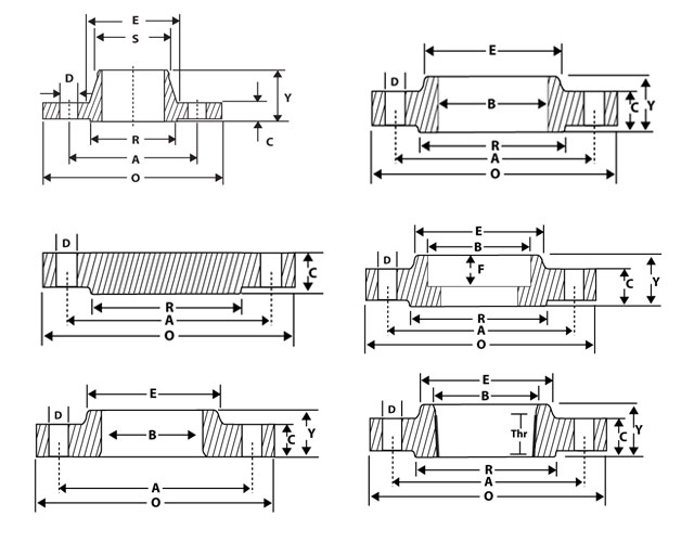
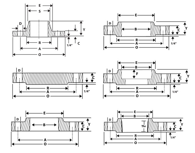
| DIMENSIONS OF CLASS 150 FLANGES (ANSI B 16.5) (in mm) | ||||||||||||||||
| Nominal Pipe Size |
Flange Dia 'O' |
Dia of Bolt Circle 'A' |
Dia of Bolt Holes 'D' |
No. of Holes |
Thk of Flange 'C' |
Diameter at Weld Bevel | Dia of Hub 'E' |
Length Through Hub | Bore 'B' | Dia of R/F R |
Depth of Socket F |
Length of Threading |
||||
| S/O & S/W Y |
W/N Y |
L/J Y |
S/O & S/W B |
L/J B |
||||||||||||
| 1/2'' | 15 | 88.9 | 60.3 | 15.9 | 4 | 11.1 | 21.3 | 30.2 | 15.9 | 47.6 | 15.9 | 22.3 | 22.9 | 34.9 | 9.5 | 15.9 |
| 3/4'' | 20 | 98.4 | 69.8 | 15.9 | 4 | 12.7 | 26.7 | 38.1 | 15.9 | 52.4 | 15.9 | 27.7 | 28.2 | 42.9 | 11.1 | 15.9 |
| 1'' | 25 | 107.9 | 79.4 | 15.9 | 4 | 14.3 | 33.5 | 49.2 | 17.5 | 55.6 | 17.5 | 34.5 | 35.0 | 50.8 | 12.7 | 17.5 |
| 1 ¼'' | 32 | 117.5 | 88.9 | 15.9 | 4 | 15.9 | 42.2 | 58.7 | 20.6 | 57.1 | 20.6 | 43.2 | 43.7 | 63.5 | 14.3 | 20.6 |
| 1 ½'' | 40 | 127.0 | 98.4 | 15.9 | 4 | 17.5 | 48.3 | 65.1 | 22.2 | 61.9 | 22.2 | 49.5 | 50.0 | 73.0 | 15.9 | 22.2 |
| 2'' | 50 | 152.4 | 120.6 | 19.0 | 4 | 19.0 | 60.4 | 77.8 | 25.4 | 63.5 | 25.4 | 62.0 | 62.5 | 92.1 | 17.5 | 25.4 |
| 2 ½'' | 65 | 177.8 | 139.7 | 19.0 | 4 | 22.2 | 73.1 | 90.5 | 28.6 | 69.8 | 28.6 | 74.7 | 75.4 | 104.8 | 19.0 | 28.6 |
| 3'' | 80 | 190.5 | 152.4 | 19.0 | 4 | 23.8 | 88.9 | 107.9 | 30.2 | 69.8 | 30.2 | 90.7 | 91.4 | 127.0 | 20.6 | 30.2 |
| 3 ½'' | 90 | 216.0 | 177.8 | 19.0 | 8 | 23.8 | 101.6 | 122.2 | 31.7 | 71.4 | 31.7 | 103.4 | 104.1 | 140.0 | 20.6 | 31.7 |
| 4'' | 100 | 228.6 | 190.5 | 19.0 | 8 | 23.8 | 114.3 | 134.9 | 33.3 | 76.2 | 33.3 | 116.1 | 116.8 | 157.2 | 23.8 | 33.3 |
| 5'' | 125 | 254.0 | 215.9 | 22.2 | 8 | 23.8 | 141.2 | 163.5 | 36.5 | 88.9 | 36.5 | 143.8 | 144.5 | 185.7 | 23.8 | 36.5 |
| 6'' | 150 | 279.4 | 241.3 | 22.2 | 8 | 25.4 | 168.4 | 192.1 | 39.7 | 88.9 | 39.7 | 170.7 | 171.4 | 215.9 | 27.0 | 39.7 |
| 8'' | 200 | 342.9 | 298.4 | 22.2 | 8 | 28.6 | 219.2 | 246.1 | 44.4 | 101.6 | 44.4 | 221.5 | 222.2 | 269.9 | 31.7 | 44.4 |
| 10'' | 250 | 406.4 | 361.9 | 25.4 | 12 | 30.2 | 273.0 | 304.8 | 49.2 | 101.6 | 49.2 | 276.3 | 277.4 | 323.8 | 33.3 | 49.2 |
| 12'' | 300 | 482.6 | 431.8 | 25.4 | 12 | 31.8 | 323.8 | 365.1 | 55.6 | 114.3 | 55.6 | 327.1 | 328.2 | 381.0 | 39.7 | 55.6 |
| 14'' | 350 | 533.4 | 476.2 | 28.6 | 12 | 34.9 | 355.6 | 400.0 | 57.1 | 127.0 | 79.4 | 359.1 | 360.2 | 412.7 | 41.3 | 57.1 |
| 16'' | 400 | 596.9 | 539.7 | 28.6 | 16 | 36.5 | 406.4 | 457.2 | 63.5 | 127.0 | 87.3 | 410.5 | 411.2 | 469.9 | 44.4 | 63.5 |
| 18'' | 450 | 635.0 | 577.8 | 31.7 | 16 | 39.7 | 457.2 | 504.8 | 68.3 | 139.7 | 96.8 | 461.8 | 462.3 | 533.4 | 49.2 | 68.3 |
| 20'' | 500 | 698.5 | 635.0 | 31.7 | 20 | 42.9 | 508.0 | 558.8 | 73.0 | 144.5 | 103.2 | 513.1 | 514.3 | 584.2 | 54.0 | 73.0 |
| 24'' | 600 | 812.8 | 749.3 | 34.9 | 20 | 47.6 | 609.6 | 663.6 | 82.5 | 152.4 | 111.1 | 615.9 | 615.9 | 692.1 | 63.5 | 82.5 |

| DIMENSIONS OF CLASS 300 FLANGES (ANSI B 16.5) (in mm) | ||||||||||||||||
| Nominal Pipe Size |
Flange Dia 'O' |
Dia of Bolt Circle 'A' |
Dia of Bolt Holes 'D' |
No. of Holes |
Thk of Flange 'C' |
Diameter at Weld Bevel | Dia of Hub 'E' |
Length Through Hub | Bore 'B' | Dia of R/F R |
Depth of Socket F |
Length of Threading |
||||
| S/O & S/W Y |
W/N Y |
L/J Y |
S/O & S/W B |
L/J B |
||||||||||||
| 1/2'' | 15 | 95.2 | 66.7 | 15.9 | 4 | 14.3 | 21.3 | 38.1 | 22.2 | 52.4 | 22.2 | 22.3 | 22.9 | 34.9 | 9.5 | 15.9 |
| 3/4'' | 20 | 117.5 | 82.5 | 19.0 | 4 | 15.9 | 26.7 | 47.6 | 25.4 | 57.1 | 25.4 | 27.7 | 28.2 | 42.9 | 11.1 | 15.9 |
| 1'' | 25 | 123.8 | 88.9 | 19.0 | 4 | 17.5 | 33.5 | 54.0 | 27.0 | 61.9 | 27.0 | 34.5 | 35.0 | 50.8 | 12.7 | 17.5 |
| 1 ¼'' | 32 | 133.3 | 98.4 | 19.0 | 4 | 19.0 | 42.2 | 63.5 | 27.0 | 65.1 | 27.0 | 43.2 | 43.7 | 63.5 | 14.3 | 20.6 |
| 1 ½'' | 40 | 155.6 | 114.3 | 22.2 | 4 | 20.6 | 48.3 | 69.8 | 30.2 | 68.3 | 30.2 | 49.5 | 50.0 | 73.0 | 15.9 | 22.2 |
| 2'' | 50 | 165.1 | 127.0 | 19.0 | 8 | 22.2 | 60.4 | 84.1 | 33.3 | 69.8 | 33.3 | 62.0 | 62.5 | 92.1 | 17.5 | 25.4 |
| 2 ½'' | 65 | 190.5 | 149.2 | 22.2 | 8 | 25.4 | 73.1 | 100.0 | 38.1 | 76.2 | 38.1 | 74.7 | 75.4 | 104.8 | 19.0 | 28.6 |
| 3'' | 80 | 209.5 | 168.3 | 22.2 | 8 | 28.6 | 88.9 | 117.5 | 42.9 | 79.4 | 42.9 | 90.7 | 91.4 | 127.0 | 20.6 | 30.2 |
| 3 ½'' | 90 | 228.5 | 184.2 | 22.2 | 8 | 30.2 | 101.6 | 133.4 | 44.5 | 81.0 | 44.5 | 103.4 | 104.1 | 140.0 | 20.6 | 31.7 |
| 4'' | 100 | 254.0 | 200.0 | 22.2 | 8 | 31.8 | 114.3 | 146.0 | 47.6 | 85.7 | 47.6 | 116.1 | 116.8 | 157.2 | 23.8 | 33.3 |
| 5'' | 125 | 279.4 | 234.9 | 22.2 | 8 | 34.9 | 141.2 | 177.8 | 50.8 | 98.4 | 50.8 | 143.8 | 144.5 | 185.7 | - | 36.5 |
| 6'' | 150 | 317.5 | 269.9 | 22.2 | 12 | 36.5 | 168.4 | 206.4 | 52.4 | 98.4 | 52.4 | 170.7 | 171.4 | 215.9 | - | 39.7 |
| 8'' | 200 | 381.0 | 330.2 | 25.4 | 12 | 41.3 | 219.2 | 260.3 | 61.9 | 111.1 | 61.9 | 221.5 | 222.2 | 269.9 | - | 44.4 |
| 10'' | 250 | 444.5 | 387.3 | 28.6 | 16 | 47.6 | 273.0 | 320.7 | 66.7 | 117.5 | 95.2 | 276.3 | 277.4 | 323.8 | - | 49.2 |
| 12'' | 300 | 520.7 | 450.8 | 31.7 | 16 | 50.8 | 323.8 | 374.6 | 73.0 | 130.2 | 101.6 | 327.1 | 328.2 | 381.0 | - | 55.6 |
| 14'' | 350 | 584.2 | 514.3 | 31.7 | 20 | 54.0 | 355.6 | 425.4 | 76.2 | 142.9 | 111.1 | 359.1 | 360.2 | 412.7 | - | 57.1 |
| 16'' | 400 | 647.7 | 571.5 | 34.9 | 20 | 57.2 | 406.4 | 482.6 | 82.5 | 146.0 | 120.6 | 410.5 | 411.2 | 469.9 | - | 63.5 |
| 18'' | 450 | 711.2 | 628.5 | 34.9 | 24 | 60.3 | 457.2 | 533.4 | 88.9 | 158.7 | 130.2 | 461.8 | 462.3 | 533.4 | - | 68.3 |
| 20'' | 500 | 774.7 | 685.8 | 34.9 | 24 | 63.5 | 508.0 | 587.4 | 95.2 | 161.9 | 139.7 | 513.1 | 514.3 | 584.2 | - | 73.0 |
| 24'' | 600 | 914.4 | 812.8 | 41.3 | 24 | 69.8 | 609.6 | 701.7 | 106.4 | 168.3 | 152.4 | 615.9 | 615.9 | 692.1 | - | 82.5 |

| DIMENSIONS OF CLASS 600 FLANGES (ANSI B 16.5) (in mm) | ||||||||||||||||
| Nominal Pipe Size |
Flange Dia 'O' |
Dia of Bolt Circle 'A' |
Dia of Bolt Holes 'D' |
No. of Holes |
Thk of Flange 'C' |
Diameter at Weld Bevel | Dia of Hub 'E' |
Length Through Hub | Bore 'B' | Dia of R/F R |
Depth of Socket F |
Length of Threading |
||||
| S/O & S/W Y |
W/N Y |
L/J Y |
S/O & S/W B |
L/J B |
||||||||||||
| 1/2'' | 15 | 95.2 | 66.7 | 15.9 | 4 | 14.3 | 21.3 | 38.1 | 22.2 | 52.4 | 22.2 | 22.3 | 22.9 | 34.9 | 9.5 | 15.9 |
| 3/4'' | 20 | 117.5 | 82.5 | 19.0 | 4 | 15.9 | 26.7 | 47.6 | 25.4 | 57.1 | 25.4 | 27.7 | 28.2 | 42.9 | 11.1 | 15.9 |
| 1'' | 25 | 123.8 | 88.9 | 19.0 | 4 | 17.5 | 33.5 | 54.0 | 27.0 | 61.9 | 27.0 | 34.5 | 35.0 | 50.8 | 12.7 | 17.5 |
| 1 ¼'' | 32 | 133.3 | 98.4 | 19.0 | 4 | 20.6 | 42.2 | 63.5 | 28.6 | 66.7 | 28.6 | 43.2 | 43.7 | 63.5 | 14.3 | 20.6 |
| 1 ½'' | 40 | 155.6 | 114.3 | 22.2 | 4 | 22.2 | 48.3 | 69.8 | 31.7 | 69.8 | 31.7 | 49.5 | 50.0 | 73.0 | 15.9 | 22.2 |
| 2'' | 50 | 165.1 | 127.0 | 19.0 | 8 | 25.4 | 60.4 | 84.1 | 36.5 | 73.0 | 36.5 | 62.0 | 62.5 | 92.1 | 17.5 | 25.4 |
| 2 ½'' | 65 | 190.5 | 149.2 | 22.2 | 8 | 28.6 | 73.1 | 100.0 | 41.3 | 79.4 | 41.3 | 74.7 | 75.4 | 104.8 | 19.0 | 28.6 |
| 3'' | 80 | 209.5 | 168.3 | 22.2 | 8 | 31.8 | 88.9 | 117.5 | 46.0 | 82.5 | 46.0 | 90.7 | 91.4 | 127.0 | - | 30.2 |
| 3 ½'' | 90 | 228.5 | 184.2 | 22.2 | 8 | 34.9 | 101.6 | 133.4 | 49.3 | 85.7 | 49.3 | 103.4 | 104.1 | 140.0 | - | 31.7 |
| 4'' | 100 | 273.0 | 215.9 | 25.4 | 8 | 38.1 | 114.3 | 152.4 | 54.0 | 101.6 | 54.0 | 116.1 | 116.8 | 157.2 | - | 33.3 |
| 5'' | 125 | 330.2 | 266.7 | 28.6 | 8 | 44.4 | 141.2 | 188.9 | 60.3 | 114.3 | 60.3 | 143.8 | 144.5 | 185.7 | - | 36.5 |
| 6'' | 150 | 355.6 | 292.1 | 28.6 | 12 | 47.6 | 168.4 | 222.2 | 66.7 | 117.5 | 66.7 | 170.7 | 171.4 | 215.9 | - | 39.7 |
| 8'' | 200 | 419.1 | 349.2 | 31.7 | 12 | 55.6 | 219.2 | 273.0 | 76.2 | 133.3 | 76.2 | 221.5 | 222.2 | 269.9 | - | 44.4 |
| 10'' | 250 | 508.0 | 431.8 | 34.9 | 16 | 63.5 | 273.0 | 342.9 | 85.7 | 152.4 | 111.2 | 276.3 | 277.4 | 323.8 | - | 49.2 |
| 12'' | 300 | 558.8 | 488.9 | 34.9 | 20 | 66.7 | 323.8 | 400.0 | 92.1 | 155.6 | 117.3 | 327.1 | 328.2 | 381.0 | - | 55.6 |
| 14'' | 350 | 603.2 | 527.0 | 38.1 | 20 | 69.9 | 355.6 | 431.8 | 93.7 | 165.1 | 127.0 | 359.1 | 360.2 | 412.7 | - | 57.1 |
| 16'' | 400 | 685.8 | 603.2 | 41.3 | 20 | 76.2 | 406.4 | 495.3 | 106.4 | 177.8 | 139.7 | 410.5 | 411.2 | 469.9 | - | 63.5 |
| 18'' | 450 | 742.9 | 654.0 | 44.4 | 24 | 82.6 | 457.2 | 546.1 | 117.5 | 184.1 | 152.4 | 461.8 | 462.3 | 533.4 | - | 68.3 |
| 20'' | 500 | 812.8 | 723.9 | 44.4 | 24 | 88.9 | 508.0 | 609.6 | 127.0 | 190.5 | 165.1 | 513.1 | 514.3 | 584.2 | - | 73.0 |
| 24'' | 600 | 939.8 | 838.2 | 50.8 | 24 | 101.6 | 609.6 | 717.5 | 139.7 | 203.2 | 184.1 | 615.9 | 615.9 | 692.1 | - | 82.5 |

| DIMENSIONS OF CLASS 900 FLANGES (ANSI B 16.5) (in mm) | ||||||||||||||||
| Nominal Pipe Size |
Flange Dia 'O' |
Dia of Bolt Circle 'A' |
Dia of Bolt Holes 'D' |
No. of Holes |
Thk of Flange 'C' |
Diameter at Weld Bevel | Dia of Hub 'E' |
Length Through Hub | Bore 'B' | Dia of R/F R |
Depth of Socket F |
Length of Threading |
||||
| S/O & S/W Y |
W/N Y |
L/J Y |
S/O & S/W B |
L/J B |
||||||||||||
| 1/2'' | 15 | 95.2 | 66.7 | 15.9 | 4 | 14.3 | 21.3 | 38.1 | 22.2 | 52.4 | 22.2 | 22.3 | 22.9 | 34.9 | 9.5 | 15.9 |
| 3/4'' | 20 | 117.5 | 82.5 | 19.0 | 4 | 15.9 | 26.7 | 47.6 | 25.4 | 57.1 | 25.4 | 27.7 | 28.2 | 42.9 | 11.1 | 15.9 |
| 1'' | 25 | 123.8 | 88.9 | 19.0 | 4 | 17.5 | 33.5 | 54.0 | 27.0 | 61.9 | 27.0 | 34.5 | 35.0 | 50.8 | 12.7 | 17.5 |
| 1 ¼'' | 32 | 133.3 | 98.4 | 19.0 | 4 | 20.6 | 42.2 | 63.5 | 28.6 | 66.7 | 28.6 | 43.2 | 43.7 | 63.5 | 14.3 | 20.6 |
| 1 ½'' | 40 | 155.6 | 114.3 | 22.2 | 4 | 22.2 | 48.3 | 69.8 | 31.7 | 69.8 | 31.7 | 49.5 | 50.0 | 73.0 | 15.9 | 22.2 |
| 2'' | 50 | 165.1 | 127.0 | 19.0 | 8 | 25.4 | 60.4 | 84.1 | 36.5 | 73.0 | 36.5 | 62.0 | 62.5 | 92.1 | 17.5 | 25.4 |
| 2 ½'' | 65 | 190.5 | 149.2 | 22.2 | 8 | 28.6 | 73.1 | 100.0 | 41.3 | 79.4 | 41.3 | 74.7 | 75.4 | 104.8 | 19.0 | 28.6 |
| 3'' | 80 | 209.5 | 168.3 | 22.2 | 8 | 31.8 | 88.9 | 117.5 | 46.0 | 82.5 | 46.0 | 90.7 | 91.4 | 127.0 | - | 30.2 |
| 3 ½'' | 90 | 228.5 | 184.2 | 22.2 | 8 | 34.9 | 101.6 | 133.4 | 49.3 | 85.7 | 49.3 | 103.4 | 104.1 | 140.0 | - | 31.7 |
| 4'' | 100 | 273.0 | 215.9 | 25.4 | 8 | 38.1 | 114.3 | 152.4 | 54.0 | 101.6 | 54.0 | 116.1 | 116.8 | 157.2 | - | 33.3 |
| 5'' | 125 | 330.2 | 266.7 | 28.6 | 8 | 44.4 | 141.2 | 188.9 | 60.3 | 114.3 | 60.3 | 143.8 | 144.5 | 185.7 | - | 36.5 |
| 6'' | 150 | 355.6 | 292.1 | 28.6 | 12 | 47.6 | 168.4 | 222.2 | 66.7 | 117.5 | 66.7 | 170.7 | 171.4 | 215.9 | - | 39.7 |
| 8'' | 200 | 419.1 | 349.2 | 31.7 | 12 | 55.6 | 219.2 | 273.0 | 76.2 | 133.3 | 76.2 | 221.5 | 222.2 | 269.9 | - | 44.4 |
| 10'' | 250 | 508.0 | 431.8 | 34.9 | 16 | 63.5 | 273.0 | 342.9 | 85.7 | 152.4 | 111.2 | 276.3 | 277.4 | 323.8 | - | 49.2 |
| 12'' | 300 | 558.8 | 488.9 | 34.9 | 20 | 66.7 | 323.8 | 400.0 | 92.1 | 155.6 | 117.3 | 327.1 | 328.2 | 381.0 | - | 55.6 |
| 14'' | 350 | 603.2 | 527.0 | 38.1 | 20 | 69.9 | 355.6 | 431.8 | 93.7 | 165.1 | 127.0 | 359.1 | 360.2 | 412.7 | - | 57.1 |
| 16'' | 400 | 685.8 | 603.2 | 41.3 | 20 | 76.2 | 406.4 | 495.3 | 106.4 | 177.8 | 139.7 | 410.5 | 411.2 | 469.9 | - | 63.5 |
| 18'' | 450 | 742.9 | 654.0 | 44.4 | 24 | 82.6 | 457.2 | 546.1 | 117.5 | 184.1 | 152.4 | 461.8 | 462.3 | 533.4 | - | 68.3 |
| 20'' | 500 | 812.8 | 723.9 | 44.4 | 24 | 88.9 | 508.0 | 609.6 | 127.0 | 190.5 | 165.1 | 513.1 | 514.3 | 584.2 | - | 73.0 |
| 24'' | 600 | 939.8 | 838.2 | 50.8 | 24 | 101.6 | 609.6 | 717.5 | 139.7 | 203.2 | 184.1 | 615.9 | 615.9 | 692.1 | - | 82.5 |
| DIMENSIONS OF CLASS 1500 FLANGES (ANSI B 16.5) (in mm) | ||||||||||||||||
| Nominal Pipe Size |
Flange Dia 'O' |
Dia of Bolt Circle 'A' |
Dia of Bolt Holes 'D' |
No. of Holes |
Thk of Flange 'C' |
Diameter at Weld Bevel | Dia of Hub 'E' |
Length Through Hub | Bore 'B' | Dia of R/F R |
Depth of Socket F |
Length of Threading |
||||
| S/O & S/W Y |
W/N Y |
L/J Y |
S/O & S/W B |
L/J B |
||||||||||||
| 1/2'' | 15 | 120.6 | 82.5 | 22.2 | 4 | 22.2 | 21.3 | 38.1 | 31.7 | 60.3 | 31.7 | 22.3 | 22.9 | 34.9 | 9.5 | 22.2 |
| 3/4'' | 20 | 130.2 | 88.9 | 22.2 | 4 | 25.4 | 26.7 | 44.4 | 34.9 | 69.8 | 34.9 | 27.7 | 28.2 | 42.9 | 11.1 | 25.4 |
| 1'' | 25 | 149.2 | 101.6 | 25.4 | 4 | 28.6 | 33.5 | 52.4 | 41.3 | 73.0 | 41.3 | 34.5 | 35.0 | 50.8 | 12.7 | 28.6 |
| 1 ¼'' | 32 | 158.7 | 111.1 | 25.4 | 4 | 28.6 | 42.2 | 63.5 | 41.3 | 73.0 | 41.3 | 43.2 | 43.7 | 63.5 | 14.3 | 30.2 |
| 1 ½'' | 40 | 177.8 | 123.8 | 28.6 | 4 | 31.8 | 48.3 | 69.8 | 44.4 | 82.5 | 44.4 | 49.5 | 50.0 | 73.0 | 15.9 | 31.7 |
| 2'' | 50 | 215.9 | 165.1 | 25.4 | 8 | 38.1 | 60.4 | 104.8 | 57.1 | 101.6 | 57.1 | 62.0 | 62.5 | 92.1 | 17.5 | 38.1 |
| 2 ½'' | 65 | 244.5 | 190.5 | 28.6 | 8 | 41.3 | 73.1 | 123.8 | 63.5 | 123.8 | 63.5 | 74.7 | 75.4 | 104.8 | 19.0 | 47.6 |
| 3'' | 80 | 266.7 | 203.2 | 31.7 | 8 | 47.6 | 88.9 | 133.3 | 73.0 | 117.5 | 73.0 | 90.7 | 91.4 | 127.0 | - | 50.8 |
| 4'' | 100 | 311.1 | 241.3 | 34.9 | 8 | 54.0 | 114.3 | 161.9 | 90.5 | 123.0 | 90.5 | 116.1 | 116.8 | 157.2 | - | 57.1 |
| 5'' | 125 | 374.6 | 292.1 | 41.3 | 8 | 73.0 | 141.2 | 196.8 | 104.8 | 155.6 | 104.8 | 143.8 | 144.5 | 185.7 | - | 63.5 |
| 6'' | 150 | 393.7 | 317.5 | 38.1 | 12 | 82.6 | 168.4 | 228.6 | 119.1 | 171.4 | 119.1 | 170.7 | 171.4 | 215.9 | - | 69.8 |
| 8'' | 200 | 482.6 | 393.7 | 44.4 | 12 | 92.1 | 219.2 | 292.1 | 142.9 | 212.7 | 142.8 | 221.5 | 222.2 | 269.9 | - | 76.2 |
| 10'' | 250 | 584.2 | 482.6 | 50.8 | 12 | 107.9 | 273.0 | 368.3 | 158.7 | 254.0 | 177.8 | 276.3 | 277.4 | 323.8 | - | 84.1 |
| 12'' | 300 | 673.1 | 571.5 | 54.0 | 16 | 123.8 | 323.8 | 450.8 | 181.0 | 282.5 | 219.1 | 327.1 | 328.2 | 381.0 | - | 92.1 |
| 14'' | 350 | 749.5 | 635.0 | 60.5 | 16 | 133.4 | 355.6 | 495.3 | - | 298.5 | 241.3 | 359.1 | 360.2 | 412.7 | - | - |
| 16'' | 400 | 825.5 | 704.9 | 66.5 | 16 | 146.1 | 406.4 | 552.5 | - | 311.2 | 260.4 | 410.5 | 411.2 | 469.9 | - | - |
| 18'' | 450 | 914.5 | 774.7 | 73.5 | 16 | 162.0 | 457.2 | 596.9 | - | 327.0 | 276.2 | 461.8 | 462.3 | 533.4 | - | - |
| 20'' | 500 | 984.0 | 831.9 | 79.5 | 16 | 177.8 | 508.0 | 641.4 | - | 355.6 | 292.1 | 513.1 | 514.3 | 584.2 | - | - |
| 24'' | 600 | 1168.5 | 990.6 | 92.0 | 16 | 203.2 | 609.6 | 762.0 | - | 406.4 | 330.2 | 615.9 | 615.9 | 692.1 | - | - |

| DIMENSIONS OF CLASS 2500 FLANGES (ANSI B 16.5) (in mm) | ||||||||||||||||
| Nominal Pipe Size |
Flange Dia 'O' |
Dia of Bolt Circle 'A' |
Dia of Bolt Holes 'D' |
No. of Holes |
Thk of Flange 'C' |
Diameter at Weld Bevel | Dia of Hub 'E' |
Length Through Hub | Bore 'B' | Dia of R/F R |
Depth of Socket F |
Length of Threading |
||||
| S/O & S/W Y |
W/N Y |
L/J Y |
S/O & S/W B |
L/J B |
||||||||||||
| 1/2'' | 15 | 133.3 | 88.9 | 22.2 | 4 | 30.2 | 21.3 | 42.9 | 39.7 | 73.3 | 39.7 | 22.3 | 22.9 | 34.9 | - | 28.6 |
| 3/4'' | 20 | 139.7 | 95.2 | 22.2 | 4 | 31.7 | 26.7 | 50.8 | 42.9 | 79.4 | 42.9 | 27.7 | 28.2 | 42.9 | - | 31.7 |
| 1'' | 25 | 158.7 | 107.9 | 25.4 | 4 | 34.9 | 33.5 | 57.1 | 47.7 | 88.9 | 47.7 | 34.5 | 35.0 | 50.8 | - | 34.9 |
| 1 ¼'' | 32 | 184.1 | 130.2 | 28.6 | 4 | 38.1 | 42.2 | 73.0 | 52.4 | 95.2 | 52.4 | 43.2 | 43.7 | 63.5 | - | 38.1 |
| 1 ½'' | 40 | 203.2 | 146.0 | 31.7 | 4 | 44.4 | 48.3 | 79.4 | 60.3 | 111.1 | 60.3 | 49.5 | 50.0 | 73.0 | - | 44.4 |
| 2'' | 50 | 234.9 | 171.4 | 28.6 | 8 | 50.8 | 60.4 | 95.2 | 69.8 | 127.0 | 69.8 | 62.0 | 62.5 | 92.1 | - | 50.8 |
| 2 ½'' | 65 | 266.7 | 196.8 | 31.7 | 8 | 57.1 | 73.1 | 114.3 | 79.4 | 142.9 | 79.4 | 74.7 | 75.4 | 104.8 | - | 57.1 |
| 3'' | 80 | 304.8 | 228.6 | 34.9 | 8 | 66.7 | 88.9 | 133.3 | 92.1 | 168.3 | 92.1 | 90.7 | 91.4 | 127.0 | - | 63.5 |
| 4'' | 100 | 355.6 | 273.0 | 41.3 | 8 | 76.2 | 114.3 | 165.1 | 107.9 | 190.5 | 107.9 | 116.1 | 116.8 | 157.2 | - | 69.8 |
| 5'' | 125 | 419.1 | 323.8 | 47.6 | 8 | 92.1 | 141.2 | 203.2 | 130.0 | 128.6 | 130.0 | 143.8 | 144.5 | 185.7 | - | 76.2 |
| 6'' | 150 | 482.6 | 368.3 | 54.0 | 8 | 107.9 | 168.4 | 234.9 | 152.4 | 273.0 | 152.4 | 170.7 | 171.4 | 215.9 | - | 82.5 |
| 8'' | 200 | 552.4 | 438.1 | 54.0 | 12 | 127.0 | 219.2 | 304.8 | 177.8 | 317.5 | 177.8 | 221.5 | 222.2 | 269.9 | - | 95.2 |
| 10'' | 250 | 673.1 | 539.7 | 66.7 | 12 | 165.1 | 273.0 | 374.6 | 228.6 | 419.1 | 228.6 | 276.3 | 277.4 | 323.8 | - | 107.9 |
| 12'' | 300 | 762.0 | 619.1 | 73.0 | 12 | 184.1 | 323.8 | 441.3 | 254.0 | 463.5 | 254.0 | 327.1 | 328.2 | 381.0 | - | 120.6 |

WELDING NECK FLANGES BORES (in inchines)
|
||||||||||||||
| Nom Pipe Size |
Outside Diam |
Sched 10 |
Sched 20 |
Sched 30 |
Std. Wall |
Sched 40 |
Sched 60 |
Extra Strong |
Sched 80 |
Sched 100 |
Sched 120 |
Sched 140 |
Sched 160 |
Double Extra Strong |
| 1/2'' | 0.840 | 0.674 | - | - | 0.622 | 0.622 | - | 0.546 | 0.546 | - | - | - | 0.464 | 0.252 |
| 3/4'' | 1.050 | 0.884 | - | - | 0.824 | 0.824 | - | 0.742 | 0.742 | - | - | - | 0.612 | 0.434 |
| 1'' | 1.315 | 1.097 | - | - | 1.049 | 1.049 | - | 0.957 | 0.957 | - | - | - | 0.815 | 0.599 |
| 1.1/4'' | 1.660 | 1.442 | - | - | 1.380 | 1.380 | - | 1.278 | 1.278 | - | - | - | 1.160 | 0.896 |
| 1.1/2'' | 1.900 | 1.682 | - | - | 1.610 | 1.610 | - | 1.500 | 1.500 | - | - | - | 1.338 | 1.100 |
| 2'' | 2.375 | 2.157 | - | - | 2.067 | 2.067 | - | 1.939 | 1.939 | - | - | - | 1.687 | 1.503 |
| 2.1/2'' | 2.875 | 2.635 | - | - | 2.469 | 2.469 | - | 2.323 | 2.323 | - | - | - | 2.125 | 1.771 |
| 3'' | 3.500 | 3.260 | - | - | 3.068 | 3.068 | - | 2.900 | 2.900 | - | - | - | 2.624 | 2.300 |
| 3-1/2'' | 4.000 | 3.760 | - | - | 3.548 | 3.548 | - | 3.364 | 3.364 | - | - | - | - | 2.728 |
| 4'' | 4.500 | 4.260 | - | - | 4.026 | 4.026 | - | 3.826 | 3.826 | - | 3.624 | - | 3.438 | 3.152 |
| 5'' | 5.563 | 5.295 | - | - | 5.047 | 5.047 | - | 4.813 | 4.813 | - | 4.563 | - | 4.313 | 4.063 |
| 6'' | 6.625 | 6.357 | - | - | 6.065 | 6.065 | - | 5.761 | 5.761 | - | 5.501 | - | 5.187 | 4.897 |
| 8'' | 8.625 | 8.329 | 8.125 | 8.071 | 7.981 | 7.981 | 7.813 | 7.625 | 7.625 | 7.437 | 7.187 | 7.001 | 6.813 | 6.875 |
| 10'' | 10.750 | 10.420 | 10.250 | 10.136 | 10.020 | 10.020 | 9.750 | 9.750 | 9.562 | 9.312 | 9.062 | 8.750 | 8.500 | 8.750 |
| 12'' | 12.750 | 10.420 | 10.250 | 12.090 | 12.000 | 11.938 | 11.626 | 11.750 | 11.374 | 11.062 | 10.750 | 10.500 | 10.126 | 10.750 |
| 14'' | 14.000 | 13.500 | 13.376 | 13.250 | 13.250 | 13.124 | 12.812 | 13.000 | 12.500 | 12.124 | 11.814 | 11.500 | 11.188 | - |
| 16'' | 16.000 | 15.500 | 15.376 | 15.250 | 15.250 | 15.000 | 14.688 | 15.000 | 14.312 | 13.938 | 13.564 | 13.124 | 12.812 | - |
| 18'' | 18.000 | 17.500 | 17.376 | 17.124 | 17.250 | 16.876 | 16.500 | 17.000 | 16.124 | 15.688 | 15.250 | 14.876 | 14.438 | - |
| 20'' | 20.000 | 19.500 | 19.250 | 19.000 | 19.250 | 18.812 | 18.376 | 19.000 | 17.938 | 17.438 | 17.000 | 16.500 | 16.062 | - |
| 24'' | 24.000 | 23.500 | 23.250 | 22.876 | 23.250 | 22.624 | 22.062 | 23.000 | 21.562 | 20.938 | 20.376 | 19.876 | 19.312 | - |
| 30'' | 30.000 | 29.376 | 29.000 | 28.750 | 29.250 | - | - | 29.000 | - | - | - | - | - | - |
| 36'' | 36.000 | 35.376 | 35.000 | 34.750 | 35.250 | 34.500 | - | 35.000 | - | - | - | - | - | - |
| 42'' | 42.000 | - | - | - | 41.250 | - | - | 41.000 | - | - | - | - | - | - |
| ANSI FLANGES WEIGHT (KGS) | ||||||||||||||||||
| Nom Pipe Size |
150# | 300# | 600# | 900# | 1500# | 2500# | ||||||||||||
| WN | S/O | B/K | WN | S/O | B/K | WN | S/O | B/K | WN | S/O | B/K | WN | S/O | B/K | WN | S/O | B/K | |
| 1/2'' | 0.7 | 0.4 | 0.5 | 0.8 | 0.7 | 0.8 | 0.9 | 0.8 | 0.8 | 2.1 | 1.8 | 1.9 | 2.1 | 1.8 | 1.9 | 3.2 | 3 | 3 |
| 3/4'' | 0.8 | 0.7 | 0.8 | 1.4 | 1.2 | 1.2 | 1.6 | 1.4 | 1.4 | 2.7 | 2.4 | 2.7 | 2.7 | 2.4 | 2.7 | 3.6 | 4 | 4.5 |
| 1'' | 1.1 | 0.8 | 0.9 | 1.7 | 1.4 | 1.5 | 1.9 | 1.7 | 1.7 | 3.9 | 3.6 | 3.7 | 3.9 | 3.6 | 3.7 | 5.4 | 5 | 5 |
| 1.1/4'' | 1.5 | 1.2 | 1.3 | 2.2 | 1.8 | 2 | 2.6 | 2.1 | 2.4 | 4.5 | 4.1 | 4.3 | 4.5 | 4.1 | 4.3 | 7.8 | 8 | 8 |
| 1.1/2'' | 1.8 | 1.4 | 1.6 | 3.2 | 2.7 | 2.9 | 3.6 | 3.1 | 3.4 | 6.2 | 5.4 | 5.9 | 6.2 | 5.4 | 5.9 | 11.5 | 11 | 11 |
| 2'' | 2.7 | 2.2 | 2.6 | 3.6 | 3.2 | 3.5 | 4.7 | 3.9 | 4.4 | 11.3 | 10.5 | 11.3 | 11.3 | 10.5 | 11.3 | 19 | 17 | 17 |
| 2.1/2'' | 4.4 | 3.5 | 4.1 | 5.4 | 4.5 | 5.3 | 4.8 | 5.4 | 6.8 | 16.3 | 15.8 | 16 | 16.3 | 15.8 | 16 | 24 | 25 | 25 |
| 3'' | 5.2 | 3.8 | 5.1 | 7.3 | 5.9 | 7.2 | 8.7 | 7.3 | 8.9 | 15 | 12.3 | 16.8 | 21 | 21.5 | 19.5 | 42.6 | 38 | 39 |
| 3-1/2'' | 6.4 | 5 | 6.5 | 8.9 | 7.5 | 9.2 | 11.6 | 9 | 12.7 | - | - | - | - | - | - | - | - | - |
| 4'' | 7.5 | 5.6 | 7.5 | 11.8 | 10 | 12.2 | 18.4 | 16.5 | 18.6 | 24 | 23.2 | 24.5 | 31.8 | 31 | 33 | 64 | 58 | 60 |
| 5'' | 9.2 | 6.5 | 9.2 | 16 | 12.5 | 16 | 31 | 28.5 | 30.8 | 38.5 | 37.5 | 39.5 | 59 | 58.8 | 60 | 111 | 95 | 101 |
| 6'' | 11.0 | 8.1 | 11.8 | 20.2 | 16.5 | 22 | 37 | 36.2 | 38 | 50 | 48.3 | 51.5 | 72 | 74 | 75 | 171 | 146 | 156 |
| 8'' | 18.4 | 13 | 20.4 | 31.2 | 25.5 | 36 | 54.5 | 51.5 | 62.2 | 85 | 75 | 89 | 124 | 112 | 125 | 261 | 220 | 242 |
| 10'' | 25.5 | 18.4 | 31 | 44.3 | 35 | 55 | 98.5 | 76.2 | 102 | 123 | 110 | 131 | 207 | 184 | 215 | 485 | 420 | 465 |
| 12'' | 37 | 28.5 | 47 | 63.5 | 52 | 82.5 | 105 | 89.5 | 132 | 168 | 146 | 187 | 306 | 264 | 316 | 698 | 590 | 665 |
| 14'' | 51 | 37.5 | 60 | 86 | 73 | 108 | 150 | 102 | 158 | 198 | 172 | 224 | 416 | - | - | - | - | - |
| 16'' | 61.5 | 44.5 | 61 | 112 | 88 | 139 | 177 | 150 | 225 | 225 | 192 | 259 | 567 | - | - | - | - | - |
| 18'' | 71.5 | 54 | 93 | 141 | 115 | 178 | 228 | 180 | 285 | 318 | 272 | 383 | 736 | - | - | - | - | - |
| 20'' | 85 | 72 | 127 | 173 | 139 | 228 | 285 | 231 | 365 | 376 | 330 | 482 | 929 | - | - | - | - | - |
| 24'' | 119 | 95 | 190 | 248 | 212 | 350 | 372 | 330 | 532 | 680 | 632 | 905 | 1504 | - | - | - | - | - |
Weldneck flanges have drilled wall thickness which is of equally same dimension existing for matching pipe. Bore will be larger if the pipe is lighter and opposite will be true if pipe is heavier and the bore will be small.
Erosion as well as turbulence is significantly reduced in pipeline as bores of flange & pipe match. Due to these reasons weldneck flanges are chosen for critical applications where high pressure and hot-cold temperatures are prevalent. The different kinds of weldneck flanges available are:
- Weld neck flanges - raised face
- Weld neck flanges - flat face

| DIMENSIONS TOLERANCES OF FLANGES (in mm) | ||||||||||||||||||||||||||||||||||||||||||||||||||||||||||||||||||||||||||||||||||||||||||||||||||||||||||||||||||||||||||||||||||||||||||||||||||||||||||||||||||||||||||||||||||||||||||||||||||||||||||||||||||||||||||||||||||||||||||||||||||||||||||||||||||||||||||||||||||||||||||||||||||||||||||||||||||||||||||||||||||||||||||||||||||||||||||||||||||||
|
|
|||||||||||||||||||||||||||||||||||||||||||||||||||||||||||||||||||||||||||||||||||||||||||||||||||||||||||||||||||||||||||||||||||||||||||||||||||||||||||||||||||||||||||||||||||||||||||||||||||||||||||||||||||||||||||||||||||||||||||||||||||||||||||||||||||||||||||||||||||||||||||||||||||||||||||||||||||||||||||||||||||||||||||||||||||||||||||||||||||
| H Not covered by ANSI - B 16.5 | ||||||||||||||||||||||||||||||||||||||||||||||||||||||||||||||||||||||||||||||||||||||||||||||||||||||||||||||||||||||||||||||||||||||||||||||||||||||||||||||||||||||||||||||||||||||||||||||||||||||||||||||||||||||||||||||||||||||||||||||||||||||||||||||||||||||||||||||||||||||||||||||||||||||||||||||||||||||||||||||||||||||||||||||||||||||||||||||||||||

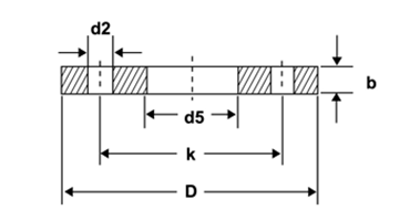
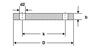
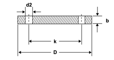
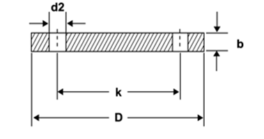
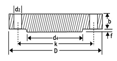
| Table
D for W. Steam Pressure upto 50 lbs per Sq. Inch (in inchines) |
Table E for W. Steam Pressure 50 lbs and upto 100 lbs per Sq. Inch (in inchines) | ||||||||||||||
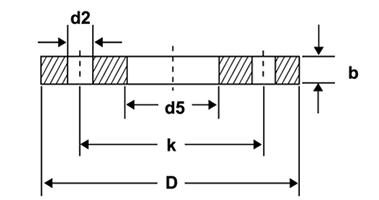
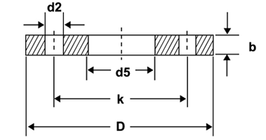
| Nominal |
Dia. of Flange |
I.D. of Flange | Dia. of Bolt Circle |
No. of |
Dia. of Bolt |
Thickness | Nominal |
Dia. of Flange |
I.D. of Flange | Dia. of Bolt Circle |
No. of |
Dia. of Bolt |
Thickness | ||
| Pipe Size | D | d5 | k | Holes | d2 | b | Pipe Size | D | d5 | k | Holes | d2 | b | ||
| 1/2" | 3.3/4" | 7/8" | 2.5/8" | 4 | 1/2" | 3/16" | 1/2" | 3.3/4" | 7/8" | 2.5/8" | 4 | 1/2" | 1/4" | ||
| 3/4" | 4" | 1.3/32" | 2.7/8" | 4 | 1/2" | 3/16" | 3/4" | 4" | 1.3/32" | 2.7/8" | 4 | 1/2" | 1/4" | ||
| 1" | 4.1/2" | 1.23/64" | 3.1/4" | 4 | 1/2" | 3/16" | 1" | 4.1/2" | 1.23/64" | 3.1/4" | 4 | 1/2" | 9/32" | ||
| 1.1/4" | 4.3/4" | 1.45/64" | 3.7/16" | 4 | 1/2" | 1/4" | 1.1/4" | 4.3/4" | 1.45/64" | 3.7/16" | 4 | 1/2" | 5/16" | ||
| 1.1/2" | 5.1/4" | 1.15/16" | 3.7/8" | 4 | 1/2" | 1/4" | 1.1/2" | 5.1/4" | 1.15/16" | 3.7/8" | 4 | 1/2" | 11/32" | ||
| 2" | 6" | 2.7/16" | 4.1/2" | 4 | 5/8" | 5/16" | 2" | 6" | 2.7/16" | 4.1/2" | 4 | 5/8" | 3/8" | ||
| 2.1/2 | 6.1/2" | 2.15/16" | 5" | 4 | 5/8" | 5/16" | 2.1/2" | 6.1/2" | 2.15/16" | 5" | 4 | 5/8" | 13/32" | ||
| 3" | 7.1/4" | 3.37/64" | 5.3/4" | 4 | 5/8" | 3/8" | 3" | 7.1/4" | 3.37/64" | 5.3/4" | 4 | 5/8" | 7/16" | ||
| 3.1/2" | 8" | 4.5/64" | 6.1/2" | 4 | 5/8" | 3/8" | 3.1/2" | 8" | 4.5/64" | 6.1/2" | 8 | 5/8" | 15/32" | ||
| 4" | 8.1/2" | 4.37/64" | 7" | 4 | 5/8" | 3/8" | 4" | 8.1/2" | 4.37/64" | 7" | 8 | 5/8" | 1/2" | ||
| 5" | 10" | 5.43/64" | 8.1/4" | 8 | 5/8" | 1/2" | 5" | 10" | 5.43/64" | 8.1/4" | 8 | 5/8" | 9/16" | ||
| 6" | 11" | 6.23/32" | 9.1/4" | 8 | 5/8" | 1/2" | 6" | 11" | 6.23/32" | 9.1/4" | 8 | 3/4" | 11/16" | ||
| 7" | 12" | 7.5/8" | 10.1/4" | 8 | 5/8" | 1/2" | 7" | 12" | 7.5/8" | 10.1/4" | 8 | 3/4" | 3/4" | ||
| 8' | 13.1/4" | 8.23/32" | 11.1/2" | 8 | 5/8" | 1/2" | 8" | 12.1/4" | 8.23/32" | 11.1/2" | 8 | 3/4" | 3/4" | ||
| 9" | 14.1/2" | 9.23/32" | 12.3/4" | 8 | 5/8" | /8" | 9" | 14.1/2" | 9.23/32" | 12.3/4" | 12 | 3/4" | 13/16" | ||
| 10" | 16" | 10.7/8" | 14" | 8 | 3/4" | 5/8"> | 10" | 16" | 10.7/8" | 14" | 12 | 3/4" | 7/8" | ||
| 12" | 18" | 12.7/8" | 16" | 12 | 3/4" | 5/8" | 12" | 18" | 12.7/8" | 16" | 12 | 7/8" | 1" | ||
| 14" | 20.3/4" | 14.9/64" | 18.1/2" | 12 | 7/8" | 3/4" | 4" | 20.3/4" | 14.9/64" | 18.1/2" | 12 | 7/8" | 1" | ||
| 16" | 22.3/4" | 16.5/32" | 20.1/2" | 12 | 7/8" | 3/4" | 6" | 22.3/4" | 16.5/32" | 20.1/2" | 12 | 7/8" | 1" | ||
| 18" | 25.1/4" | 18.3/16" | 23" | 12 | 7/8" | 7/8" | 18" | 25.1/4" | 18.3/16" | 23" | 16 | 7/8" | 1.1/8" | ||
| 20" | 27.3/4" | 20.13/16" | 25.1/4" | 16 | 7/8" | 1" | 20" | 27.3/4" | 20.13/16" | 25.1/4" | 16 | 7/8" | 1.1/4" | ||
| 24" | 32.1/2" | 24.1/4" | 29.3/4" | 16 | 1" | 1.1/8" | 24" | 32.1/2" | 24.1/4" | 29.3/4" | 16 | 1" | 1.1/2" | ||
| Table
F for W. Steam Pressure 100 lbs per Sq. Inch (in inchines) |
Table
H for W. Steam Pressure 150 lbs and upto 250 lbs per Sq. Inch (in inchines) |
|||||||||||||
| Nominal |
Dia. of Flange |
I.D. of Flange | Dia. of Bolt Circle |
No. of |
Dia. of Bolt |
Thickness | Nominal |
Dia. of Flange |
I.D. of Flange | Dia. of Bolt Circle |
No. of |
Dia. of Bolt |
Thickness | |
| Pipe Size | D | d5 | k | Holes | d2 | b | Pipe Size | D | d5 | k | Holes | d2 | b | |
| 1/2" | 3.3/4" | 7/8" | 2.5/8" | 4 | 1/2" | 3/8" | 1/2" | 4.1/2" | 7/8" | 3.1/4" | 4 | 5/8" | 1/2" | |
| 3/4" | 4" | 1.3/32" | 2.7/8" | 4 | 1/2" | 3/8" | 3/4" | 4.1/2" | 1.3/32" | 3.1/4" | 4 | 5/8" | 1/2" | |
| 1" | 4.3/4" | 1.23/64" | 3.7/16" | 4 | 5/8" | 3/8" | 1" | 4.3/4" | 1.23/64" | 33.7/16" | 4 | 5/8" | 9/16" | |
| 1.1/4" | 5.1/4" | 1.45/64" | 3.7/8" | 4 | 5/8" | 1/2" | 1.1/4" | 5.1/4" | 1.45/64" | 3.7/8" | 4 | 5/8" | 11/16" | |
| 1.1/2" | 5.1/2" | 1.15/16" | 4.1/8" | 4 | 5/8" | 1/2" | 1.1/2" | 5.1/2" | 1.15/16" | 4.1/8" | 4 | 5/8" | 11/16" | |
| 2" | 6.1/2" | 2.7/16" | 5" | 4 | 5/8" | 5/8" | 2" | 6.1/2" | 2.7/16" | 5" | 4 | 5/8" | 3/4" | |
| 2.1/2 | 7.1/4" | 2.15/16" | 5.3/4" | 8 | 5/8" | 5/8" | 2.1/2" | 7.1/4" | 2.15/16" | 5.3/4" | 8 | 5/8" | 3/4" | |
| 3" | 8" | 3.37/64" | 6.1/2" | 8 | 5/8" | 5/8" | 3" | 8" | 3.37/64" | 6.1/2" | 8 | 5/8" | 7/8" | |
| 3.1/2" | 8.1/2" | 4.5/64" | 7" | 8 | 5/8" | 3/4" | 3.1/2" | 8.1/2" | 4.5/64" | 7" | 8 | 5/8" | 7/8" | |
| 4" | 9" | 4.37/64" | 7.1/2" | 8 | 5/8" | 3/4" | 4" | 9" | 4.37/64" | 7.1/2" | 8 | 5/8" | 1" | |
| 5" | 11" | 5.43/64" | 9.1/4" | 8 | 3/4" | 7/8" | 5" | 11" | 5.43/64" | 9.1/4" | 8 | 3/4" | 1.1/8" | |
| 6" | 12" | 6.23/32" | 10.1/4" | 12 | 3/4" | 7/8" | 6" | 12" | 6.23/32" | 10.1/4" | 12 | 3/4" | 1.1/8" | |
| 7" | 13.1/4" | 7.5/8" | 11.1/2" | 12 | 3/4" | 7/8" | 7" | 13.1/4" | 7.5/8" | 11.1/2" | 12 | 3/4" | 1.1/4" | |
| 8' | 14.1/2" | 8.23/32" | 12.3/4" | 12 | 3/4" | 1" | 8" | 14.1/2" | 8.23/32" | 12.3/4" | 12 | 3/4" | 1.1/4" | |
| 9" | 16" | 9.23/32" | 14" | 12 | 7/8" | 1" | 9" | 16" | 9.23/32" | 14" | 12 | 7/8" | 1.3/8" | |
| 10" | 17" | 10.7/8" | 15" | 12 | 7/8" | 1" | 10" | 17" | 10.7/8" | 15" | 12 | 7/8" | 1.3/8" | |
| 12" | 19.1/4" | 12.7/8" | 17.1/4" | 16 | 7/8" | 1/1/8" | 12" | 19.1/4" | 12.7/8" | 17.1/4" | 16 | 7/8" | 1.1/2" | |
| 14" | 21.3/4" | 14.9/64" | 19.1/2" | 16 | 1" | 1.1/4" | 4" | 21.3/4" | 14.9/64" | 19.1/2" | 16 | 1" | 1.5/8" | |
| 16" | 24" | 16.5/32" | 21.3/4" | 20 | 1" | 1.1/4" | 6" | 24" | 16.5/32" | 21.3/4" | 20 | 1" | 1.3/4" | |
| 18" | 26.1/2" | 18.3/16" | 24" | 20 | 1.1/8" | 1.3/8" | 18" | 26.1/2" | 18.3/16" | 24" | 20 | 1.1/8" | 1.7/8" | |
| 20" | 29" | 20.13/16" | 26.1/2" | 24 | 1.1/8" | 1.1/2" | 20" | 29" | 20.13/16" | 26.1/2" | 24 | 1.1/8" | 2" | |
| 24" | 33.1/2" | 24.1/4" | 30.3/4" | 24 | 1.1/4" | 1.5/8" | 24" | 33.1/2" | 24.1/4" | 30.3/4" | 24 | 1.1/4" | 2.1/4" | |
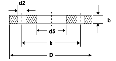
| DIN 2502 PN 16 (in mm) | ||||||||
| Nominal Pipe Size | Diameter of | Flange Dia | Flange I.D | Thk of Flanges | Dia of Bolt Cirlce | No. of | Dia of Bolt Holes | |
| DN | Pipe | D | D5 | B | K | holes | D2 | KG |
| 10 | 17.20 | 90 | 17.70 | 14 | 60 | 4 | 14 | 0.60 |
| 15 | 21.30 | 95 | 22.00 | 14 | 65 | 4 | 14 | 0.67 |
| 20 | 26.90 | 105 | 27.60 | 16 | 75 | 4 | 14 | 0.94 |
| 25 | 33.70 | 115 | 34.40 | 16 | 85 | 4 | 14 | 1.11 |
| 32 | 42.40 | 140 | 43.10 | 16 | 100 | 4 | 18 | 1.62 |
| 40 | 48.30 | 150 | 49.00 | 16 | 110 | 4 | 18 | 1.85 |
| 50 | 60.30 | 165 | 61.10 | 18 | 125 | 4 | 18 | 2.46 |
| 65 | 76.10 | 185 | 77.10 | 18 | 145 | 4 | 18 | 2.99 |
| 80 | 88.90 | 200 | 90.30 | 20 | 160 | 8 | 18 | 3.61 |
| 100 | 114.30 | 220 | 115.90 | 20 | 180 | 8 | 18 | 3.99 |
| 125 | 139.70 | 250 | 141.60 | 22 | 210 | 8 | 18 | 5.41 |
| 150 | 168.30 | 285 | 170.50 | 22 | 240 | 8 | 22 | 6.55 |
| 175 | 193.70 | 315 | 196.10 | 24 | 270 | 8 | 22 | 8.42 |
| 200 | 219.10 | 340 | 221.80 | 24 | 295 | 12 | 22 | 8.97 |
| 250 | 273.00 | 405 | 276.20 | 26 | 355 | 12 | 26 | 12.76 |
| 300 | 323.90 | 460 | 327.60 | 28 | 410 | 12 | 26 | 16.60 |
| 350 | 355.60 | 520 | 359.70 | 30 | 470 | 16 | 26 | 24.08 |
| 400 | 406.40 | 580 | 411.00 | 32 | 525 | 16 | 30 | 30.20 |
| 450 | 457.00 | 640 | 462.30 | 38 | 585 | 20 | 30 | 41.67 |
| 500 | 508.00 | 715 | 513.60 | 38 | 650 | 20 | 33 | 52.87 |
| 600 | 610.00 | 840 | 616.50 | 42 | 770 | 20 | 36 | 77.58 |
| 700 | 711.00 | 910 | 716.00 | 44 | 840 | 24 | 36 | 77.13 |
| 800 | 813.00 | 1025 | 818.00 | 50 | 950 | 24 | 39 | 106.35 |
| 900 | 914.00 | 1125 | 920.00 | 54 | 1050 | 28 | 39 | 125.39 |
| 1000 | 1016.00 | 1255 | 1022.00 | 60 | 1170 | 28 | 42 | 177.99 |
| DIN 2503 PN25 (in mm) | DIN 2503 PN40 (in mm) | |||||||||||||||||
| Nominal Pipe Size | Diameter of | Flange I.D | Flange Dia | Thk of Flange | Dia of Bolt Circle | No. of | Dia of Bolt Holes | Nominal Pipe Size | Diameter of | Flange I.D | Flange Dia | Thk of Flange | Dia of Bolt Cirlce | No. of | Dia of Bolt Holes | |||
| DN | Pipe | D5 | D | B | K | holes | D2 | KG | DN | Pipe | D5 | D | B | K | holes | D2 | KG | |
| 10 | 17.20 | 17.70 | 90 | 16 | 60 | 4 | 14 | 0.69 | 10 | 17.20 | 17.70 | 90 | 16 | 60 | 4 | 14 | 0.69 | |
| 15 | 21.30 | 22.00 | 95 | 16 | 65 | 4 | 14 | 0.77 | 15 | 21.30 | 22.00 | 95 | 16 | 65 | 4 | 14 | 0.77 | |
| 20 | 26.90 | 27.60 | 105 | 18 | 75 | 4 | 14 | 1.05 | 20 | 26.90 | 27.60 | 105 | 18 | 75 | 4 | 14 | 1.05 | |
| 25 | 33.70 | 34.40 | 115 | 18 | 85 | 4 | 14 | 1.25 | 25 | 33.70 | 34.40 | 115 | 18 | 85 | 4 | 14 | 1.25 | |
| 32 | 42.40 | 43.10 | 140 | 18 | 100 | 4 | 18 | 1.83 | 32 | 42.40 | 43.10 | 140 | 18 | 100 | 4 | 18 | 1.83 | |
| 40 | 48.30 | 49.00 | 150 | 18 | 110 | 4 | 18 | 2.09 | 40 | 48.30 | 49.00 | 150 | 18 | 110 | 4 | 18 | 2.09 | |
| 50 | 60.30 | 61.10 | 165 | 20 | 125 | 4 | 18 | 2.74 | 50 | 60.30 | 61.10 | 165 | 20 | 125 | 4 | 18 | 2.74 | |
| 65 | 76.10 | 77.10 | 185 | 22 | 145 | 8 | 18 | 3.48 | 65 | 76.10 | 77.10 | 185 | 22 | 145 | 8 | 18 | 3.48 | |
| 80 | 88.90 | 90.30 | 200 | 24 | 160 | 8 | 18 | 4.33 | 80 | 88.90 | 90.30 | 200 | 24 | 160 | 8 | 18 | 4.33 | |
| 100 | 114.30 | 115.90 | 235 | 24 | 190 | 8 | 22 | 5.61 | 100 | 114.30 | 115.90 | 235 | 24 | 190 | 8 | 22 | 5.61 | |
| 125 | 139.70 | 141.60 | 270 | 26 | 220 | 8 | 26 | 7.60 | 125 | 139.70 | 141.60 | 270 | 26 | 220 | 8 | 26 | 7.60 | |
| 150 | 168.30 | 170.50 | 300 | 28 | 250 | 8 | 26 | 9.58 | 150 | 168.30 | 170.50 | 300 | 28 | 250 | 8 | 26 | 9.58 | |
| 175 | 193.70 | 196.10 | 330 | 28 | 280 | 12 | 26 | 10.76 | 175 | 193.70 | 196.10 | 350 | 32 | 295 | 12 | 30 | 14.45 | |
| 200 | 219.10 | 221.80 | 360 | 30 | 310 | 12 | 26 | 13.37 | 200 | 219.10 | 221.80 | 375 | 34 | 320 | 12 | 30 | 16.90 | |
| 250 | 273.00 | 276.20 | 425 | 32 | 370 | 12 | 30 | 18.45 | 250 | 273.00 | 276.20 | 450 | 38 | 385 | 12 | 33 | 26.51 | |
| 300 | 323.90 | 327.60 | 485 | 34 | 430 | 16 | 30 | 23.79 | 300 | 323.90 | 327.60 | 515 | 42 | 450 | 16 | 33 | 36.38 | |
| 350 | 355.60 | 359.70 | 555 | 38 | 490 | 16 | 33 | 37.77 | 350 | 355.60 | 359.70 | 580 | 46 | 510 | 16 | 36 | 52.83 | |
| 400 | 406.40 | 411.00 | 620 | 40 | 550 | 16 | 36 | 45.41 | 400 | 406.40 | 411.00 | 660 | 50 | 585 | 16 | 39 | 74.71 | |
| 500 | 508.00 | 513.60 | 730 | 44 | 660 | 20 | 36 | 65.97 | 500 | 508.00 | 513.60 | 755 | 52 | 670 | 20 | 42 | 86.87 | |
| 600 | 610.00 | 616.50 | 845 | 50 | 770 | 20 | 39 | 93.57 | 600 | 610.00 | 616.50 | 890 | 54 | 795 | 20 | 48 | 121.84 | |
| 700 | 711.00 | 716.00 | 960 | 52 | 875 | 24 | 42 | 117.53 | 700 | 711.00 | 716.00 | 995 | 58 | 900 | 24 | 48 | 150.93 | |
| 800 | 813.00 | 818.00 | 1085 | 56 | 990 | 24 | 48 | 156.34 | 800 | 813.00 | 818.00 | 1140 | 64 | 1030 | 24 | 56 | 219.08 | |
| 900 | 914.00 | 920.00 | 1185 | 62 | 1090 | 28 | 48 | 188.57 | 900 | 914.00 | 920.00 | 1250 | 70 | 1140 | 28 | 56 | 271.16 | |
| 1000 | 1016.00 | 1022.00 | 1320 | 68 | 1210 | 28 | 56 | 255.79 | 1000 | 1016.00 | 1022.00 | 1360 | 78 | 1250 | 28 | 56 | 344.95 | |
| DIN 2527 PN6 (in mm) | DIN 2527 PN10 (in mm) | |||||||||||||
| Nominal Pipe Size | Flange Dia | Thk of Flange | Dia of Bolt Circle | No. of | Dia of Bolt Holes | Nominal Pipe Size | Flange Dia | Thk of Flange | Dia of Bolt Circle | No. of | Dia of Bolt Holes | |||
| DIN | D | B | K | holes | D2 | KG | DIN | D | B | K | holes | D2 | KG | |
| 10 | 75 | 12 | 50 | 4 | 11 | 0.38 | 10 | 90 | 14 | 60 | 4 | 14 | 0.63 | |
| 15 | 80 | 12 | 55 | 4 | 11 | 0.44 | 15 | 95 | 14 | 65 | 4 | 14 | 0.71 | |
| 20 | 90 | 14 | 65 | 4 | 11 | 0.66 | 20 | 105 | 16 | 75 | 4 | 14 | 1.01 | |
| 25 | 100 | 14 | 75 | 4 | 11 | 0.82 | 25 | 115 | 16 | 85 | 4 | 14 | 1.23 | |
| 32 | 120 | 14 | 90 | 4 | 14 | 1.18 | 32 | 140 | 16 | 100 | 4 | 18 | 1.81 | |
| 40 | 130 | 14 | 100 | 4 | 14 | 1.39 | 40 | 150 | 16 | 110 | 4 | 18 | 2.09 | |
| 50 | 140 | 14 | 110 | 4 | 14 | 1.62 | 50 | 165 | 18 | 125 | 4 | 18 | 2.88 | |
| 65 | 160 | 14 | 130 | 4 | 14 | 2.14 | 65 | 185 | 18 | 145 | 4 | 18 | 3.65 | |
| 80 | 190 | 16 | 150 | 4 | 48 | 3.43 | 80 | 200 | 20 | 160 | 4 | 18 | 4.61 | |
| 100 | 210 | 16 | 170 | 4 | 18 | 4.22 | 100 | 220 | 20 | 180 | 4 | 18 | 5.65 | |
| 125 | 240 | 18 | 200 | 8 | 18 | 6.10 | 125 | 250 | 22 | 210 | 8 | 18 | 8.13 | |
| 150 | 265 | 18 | 225 | 8 | 18 | 7.51 | 150 | 285 | 22 | 240 | 8 | 22 | 10.49 | |
| 175 | 295 | 20 | 255 | 8 | 18 | 10.41 | 175 | 315 | 24 | 270 | 8 | 22 | 14.11 | |
| 200 | 320 | 20 | 280 | 8 | 18 | 12.31 | 200 | 340 | 24 | 295 | 8 | 22 | 16.53 | |
| 250 | 375 | 22 | 335 | 12 | 18 | 18.55 | 250 | 395 | 26 | 350 | 12 | 22 | 24.08 | |
| 300 | 440 | 22 | 395 | 12 | 22 | 25.47 | 300 | 445 | 26 | 400 | 12 | 22 | 30.81 | |
| 350 | 490 | 22 | 445 | 12 | 22 | 31.78 | 350 | 505 | 26 | 460 | 12 | 22 | 39.64 | |
| 400 | 540 | 22 | 495 | 16 | 22 | 38.50 | 400 | 565 | 26 | 515 | 16 | 26 | 49.44 | |
| 500 | 645 | 24 | 600 | 20 | 22 | 60.13 | 500 | 670 | 28 | 620 | 20 | 26 | 75.16 | |
| 600 | 755 | 28 | 705 | 20 | 26 | 96.07 | 600 | 780 | 30 | 725 | 20 | 30 | 109.20 | |
| 700 | 860 | 30 | 810 | 24 | 26 | 133.80 | 700 | 895 | 32 | 840 | 24 | 30 | 153.77 | |
| 800 | 975 | 32 | 920 | 24 | 30 | 183.29 | 800 | 1015 | 36 | 950 | 24 | 33 | 222.86 | |
| 900 | 1075 | 36 | 1020 | 24 | 30 | 251.70 | 900 | 1115 | 40 | 1050 | 24 | 33 | 299.08 | |
| 1000 | 1175 | 42 | 1120 | 28 | 30 | 350.98 | 1000 | 1230 | 46 | 1160 | 28 | 36 | 418.78 | |
| DIN 2527 PN16 (in mm) | DIN 2527 PN25 (in mm) | |||||||||||||
| Nominal Pipe Size | Flange Dia | Thk of Flange | Dia of Bolt Circle | No. of | Dia of Bolt Holes | Nominal Pipe Size | Flange Dia | Thk of Flange | Dia of Bolt Circle | No. of | Dia of Bolt Holes | |||
| DIN | D | B | K | holes | D2 | KG | DIN | D | B | K | holes | D2 | KG | |
| 10 | 90 | 14 | 60 | 4 | 14 | 0.63 | 90 | 90 | 16 | 60 | 4 | 14 | 0.72 | |
| 15 | 95 | 14 | 65 | 4 | 14 | 0.71 | 95 | 95 | 16 | 65 | 4 | 14 | 0.81 | |
| 20 | 105 | 16 | 75 | 4 | 14 | 1.01 | 105 | 105 | 18 | 75 | 4 | 14 | 1.14 | |
| 25 | 115 | 16 | 85 | 4 | 14 | 1.23 | 115 | 115 | 18 | 85 | 4 | 14 | 1.38 | |
| 32 | 140 | 16 | 100 | 4 | 18 | 1.81 | 140 | 140 | 18 | 100 | 4 | 18 | 2.03 | |
| 40 | 150 | 16 | 110 | 4 | 18 | 2.09 | 150 | 150 | 18 | 110 | 4 | 18 | 2.35 | |
| 50 | 165 | 18 | 125 | 4 | 18 | 2.88 | 165 | 165 | 20 | 125 | 4 | 18 | 3.20 | |
| 65 | 185 | 18 | 145 | 4 | 18 | 3.65 | 185 | 185 | 22 | 145 | 4 | 18 | 4.29 | |
| 80 | 200 | 20 | 160 | 8 | 18 | 4.61 | 200 | 200 | 24 | 160 | 8 | 18 | 5.54 | |
| 100 | 220 | 20 | 180 | 8 | 18 | 5.65 | 235 | 220 | 24 | 190 | 8 | 22 | 7.60 | |
| 125 | 250 | 22 | 210 | 8 | 18 | 8.13 | 270 | 250 | 26 | 220 | 8 | 26 | 10.82 | |
| 150 | 285 | 22 | 240 | 8 | 22 | 10.49 | 300 | 285 | 28 | 250 | 8 | 26 | 14.60 | |
| 175 | 315 | 24 | 270 | 8 | 22 | 14.11 | 330 | 315 | 28 | 280 | 8 | 26 | 17.40 | |
| 200 | 340 | 24 | 295 | 12 | 22 | 16.26 | 360 | 340 | 30 | 310 | 12 | 26 | 22.47 | |
| 250 | 405 | 26 | 355 | 12 | 26 | 24.99 | 425 | 405 | 32 | 370 | 12 | 30 | 33.51 | |
| 300 | 460 | 28 | 410 | 12 | 26 | 35.13 | 485 | 460 | 34 | 430 | 12 | 30 | 46.29 | |
| 350 | 520 | 30 | 470 | 16 | 26 | 48.01 | 555 | 520 | 38 | 490 | 16 | 33 | 68.08 | |
| 400 | 580 | 32 | 525 | 16 | 30 | 83.53 | 620 | 580 | 40 | 550 | 16 | 36 | 89.59 | |
| 500 | 715 | 36 | 650 | 20 | 33 | 108.63 | 730 | 715 | 45 | 660 | 20 | 36 | 140.66 | |
| 600 | 780 | 38 | 770 | 20 | 36 | 136.47 | 845 | 780 | 48 | 770 | 20 | 39 | 202.30 | |
| 700 | 895 | 40 | 840 | 24 | 36 | 189.87 | 960 | 895 | 50 | 875 | 24 | 42 | 271.05 | |
| 800 | 1015 | 44 | 950 | 24 | 39 | 269.57 | 1085 | 1015 | 54 | 990 | 24 | 48 | 373.52 | |
| 900 | 1115 | 48 | 1050 | 28 | 39 | 355.31 | 1185 | 1115 | 58 | 1090 | 28 | 48 | 479.07 | |
| 1000 | 1230 | 52 | 1170 | 28 | 42 | 469.20 | 1320 | 1230 | 62 | 1210 | 28 | 56 | 632.47 | |
| DIN 2527 PN40 (in mm) | DIN 2527 PN64 (in mm) | |||||||||||||
| Nominal Pipe Size | Flanges Dia | Thk of Flange | Dia of Bolt Circle | No. of | Dia of Bolt Holes | Nominal Pipe Size | Flanges Dia | Thk of Flange | Dia of Bolt Circle | No. of | Dia of Bolt Holes | |||
| DIN | D | B | K | holes | D2 | KG | DIN | D | B | K | holes | D2 | KG | |
| 10 | 90 | 16 | 60 | 4 | 14 | 0.72 | 10 | 90 | 20 | 70 | 4 | 14 | 1.04 | |
| 15 | 95 | 16 | 65 | 4 | 14 | 0.81 | 15 | 95 | 20 | 75 | 4 | 14 | 1.16 | |
| 20 | 105 | 18 | 75 | 4 | 14 | 1.14 | 20 | 105 | 24 | 100 | 4 | 18 | 2.54 | |
| 25 | 115 | 18 | 85 | 4 | 14 | 1.38 | 25 | 115 | 24 | 110 | 4 | 22 | 3.07 | |
| 32 | 140 | 18 | 100 | 4 | 18 | 2.03 | 32 | 140 | 26 | 125 | 4 | 22 | 3.97 | |
| 40 | 150 | 18 | 110 | 4 | 18 | 2.35 | 40 | 150 | 26 | 135 | 4 | 22 | 4.51 | |
| 50 | 165 | 20 | 125 | 4 | 18 | 3.20 | 50 | 165 | 26 | 160 | 4 | 22 | 5.69 | |
| 65 | 185 | 22 | 145 | 8 | 18 | 4.29 | 65 | 185 | 28 | 170 | 8 | 22 | 6.88 | |
| 80 | 200 | 24 | 160 | 8 | 18 | 5.54 | 80 | 200 | 30 | 200 | 8 | 26 | 9.99 | |
| 100 | 235 | 24 | 190 | 8 | 22 | 7.60 | 100 | 235 | 34 | 240 | 8 | 30 | 15.91 | |
| 125 | 270 | 26 | 220 | 8 | 26 | 10.82 | 125 | 270 | 36 | 280 | 8 | 33 | 23.32 | |
| 150 | 300 | 28 | 250 | 8 | 26 | 14.60 | 150 | 300 | 40 | 310 | 8 | 33 | 30.35 | |
| 175 | 350 | 32 | 295 | 12 | 30 | 22.04 | 175 | 350 | 42 | 345 | 12 | 36 | 39.17 | |
| 200 | 375 | 34 | 320 | 12 | 30 | 27.21 | 200 | 375 | 46 | 400 | 12 | 38 | 56.64 | |
| 250 | 450 | 38 | 385 | 12 | 33 | 44.38 | 250 | 450 | 52 | 460 | 12 | 36 | 81.14 | |
| 300 | 515 | 42 | 450 | 16 | 33 | 64.17 | 300 | 515 | 56 | 525 | 16 | 39 | 112.95 | |
| 350 | 580 | 46 | 510 | 16 | 36 | 89.52 | 350 | 580 | 60 | 585 | 16 | 42 | 152.30 | |
| 400 | 660 | 50 | 585 | 16 | 39 | 126.76 | 400 | 660 | - | - | 16 | - | - | |
| 500 | 755 | 56 | 670 | 20 | 42 | 184.63 | 500 | 755 | - | - | 20 | - | - | |
| 600 | 890 | 62 | 795 | 20 | 48 | 285.17 | 600 | 890 | - | - | 20 | - | - | |
| 700 | 995 | 64 | 900 | 24 | 48 | 368.83 | 700 | 995 | - | - | 24 | - | - | |
| 800 | 1140 | 70 | 1030 | 24 | 56 | 528.39 | 800 | 1140 | - | - | 24 | - | - | |
| 900 | 1250 | 76 | 1140 | 28 | 56 | 690.99 | 900 | 1250 | - | - | 28 | - | - | |
| 1000 | 1360 | 84 | 1250 | 28 | 56 | 912.42 | 1000 | 1360 | - | - | 28 | - | - | |
| DIN 2527 PN100 (in mm) | ||||||||
| Nominal Pipe Size | Flange Dia | Thk of Flange | Dia of Bolt Circle | Dia of R/F | Thk of R/F | No. of | Dia of Bolt Holes | |
| DN | D | B | K | D4 | F | Holes | D2 | KG |
| 10 | 100 | 20 | 70 | 40 | 2 | 4 | 14 | 1.04 |
| 15 | 105 | 20 | 75 | 45 | 2 | 4 | 14 | 1.16 |
| 25 | 140 | 24 | 100 | 68 | 2 | 4 | 18 | 2.54 |
| 32 | 155 | 24 | 110 | 78 | 2 | 4 | 22 | 3.07 |
| 40 | 170 | 26 | 125 | 88 | 3 | 4 | 22 | 3.97 |
| 50 | 195 | 28 | 145 | 102 | 3 | 4 | 26 | 5.64 |
| 65 | 220 | 30 | 170 | 122 | 3 | 8 | 26 | 7.43 |
| 80 | 230 | 32 | 180 | 138 | 3 | 8 | 26 | 8.84 |
| 100 | 265 | 36 | 210 | 162 | 3 | 8 | 30 | 13.31 |
| 125 | 315 | 40 | 250 | 188 | 3 | 8 | 33 | 21.30 |
| 150 | 355 | 44 | 290 | 218 | 3 | 12 | 33 | 29.43 |
| 175 | 385 | 48 | 320 | 260 | 3 | 12 | 33 | 38.75 |
| 200 | 430 | 52 | 360 | 285 | 3 | 12 | 36 | 52.66 |
| 250 | 505 | 60 | 430 | 345 | 3 | 12 | 39 | 85.41 |
| 300 | 585 | 68 | 500 | 410 | 4 | 16 | 42 | 128.05 |
| 350 | 655 | 74 | 560 | 465 | 4 | 16 | 48 | 174.53 |
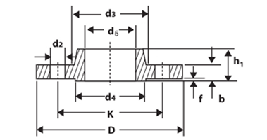
| DIN 2565 PN 6 (in mm) | |||||||||||
| Nominal Pipe Size | Flange Dia | Flange I.D | Thk of Flange | Dia of Bolt Cirlce | Length Through Hub | Dia of Hub | Dia of R/F | Thk of R/F | No. of | Dia of Bolt Holes | |
| DN | D | D5 | B | K | H1 | D3 | D4 | F | holes | D2 | KG |
| 6 | 65 | 11.7 | 10 | 40 | 18 | 18 | 25 | 2 | 4 | 11.5 | 0.19 |
| 8 | 70 | 15.0 | 10 | 45 | 18 | 22 | 30 | 2 | 4 | 11.5 | 0.23 |
| 10 | 75 | 17.70 | 12 | 50 | 20 | 25 | 35 | 2 | 4 | 11.5 | 0.32 |
| 15 | 80 | 22.00 | 12 | 55 | 20 | 30 | 40 | 2 | 4 | 11.5 | 0.37 |
| 20 | 90 | 27.60 | 14 | 65 | 24 | 40 | 50 | 2 | 4 | 11.5 | 0.58 |
| 25 | 100 | 34.40 | 14 | 75 | 24 | 50 | 60 | 2 | 4 | 11.5 | 0.73 |
| 32 | 120 | 43.10 | 14 | 90 | 26 | 60 | 70 | 2 | 4 | 14.0 | 1.05 |
| 40 | 130 | 49.00 | 14 | 100 | 26 | 70 | 80 | 3 | 4 | 14.0 | 1.20 |
| 50 | 140 | 61.10 | 14 | 110 | 28 | 80 | 90 | 3 | 4 | 14.0 | 1.54 |
| 65 | 160 | 77.10 | 14 | 130 | 32 | 100 | 110 | 3 | 4 | 14.0 | 1.87 |
| 80 | 190 | 90.30 | 16 | 150 | 34 | 110 | 128 | 3 | 4 | 18.0 | 2.78 |
| 100 | 210 | 115.90 | 16 | 170 | 38 | 130 | 148 | 3 | 4 | 18.0 | 3.07 |
| 150 | 240 | 170.50 | 18 | 200 | 40 | 160 | 178 | 3 | 8 | 18.0 | 4.33 |
| 200 | 285 | 221.80 | 18 | 225 | 44 | 185 | 202 | 3 | 8 | 18.0 | 4.81 |
| DIN 2566 PN 16 (in mm) | |||||||||||
| Nominal Pipe Size | Flange Dia | Flange I.D | Thk of Flange | Dia of Bolt Cirlce | Length Through Hub | Dia of Hub | Dia of R/F | Thk of R/F | No. of | Dia of Bolt Holes | |
| DN | D | D5 | B | K | H1 | D3 | D4 | F | holes | D2 | KG |
| 6 | 75 | 11.7 | 12 | 50 | 18 | 20 | 32 | 2 | 4 | 11 | 0.33 |
| 8 | 80 | 15.0 | 12 | 55 | 18 | 25 | 38 | 2 | 4 | 11 | 0.39 |
| 10 | 90 | 17.70 | 14 | 60 | 20 | 30 | 40 | 2 | 4 | 14 | 0.56 |
| 15 | 95 | 22.00 | 14 | 65 | 20 | 35 | 45 | 2 | 4 | 14 | 0.62 |
| 20 | 105 | 27.60 | 16 | 75 | 24 | 45 | 58 | 2 | 4 | 14 | 0.92 |
| 25 | 115 | 34.40 | 16 | 85 | 24 | 52 | 68 | 2 | 4 | 14 | 1.10 |
| 32 | 140 | 43.10 | 16 | 100 | 26 | 60 | 78 | 2 | 4 | 18 | 1.59 |
| 40 | 150 | 49.00 | 16 | 110 | 26 | 70 | 88 | 3 | 4 | 18 | 1.77 |
| 50 | 165 | 61.10 | 18 | 125 | 28 | 85 | 102 | 3 | 4 | 18 | 2.41 |
| 65 | 185 | 77.10 | 18 | 145 | 32 | 105 | 122 | 3 | 4 | 18 | 3.13 |
| 80 | 200 | 90.30 | 20 | 160 | 34 | 118 | 138 | 3 | 4 | 18 | 3.95 |
| 100 | 220 | 115.90 | 20 | 180 | 38 | 140 | 158 | 3 | 8 | 18 | 4.38 |
| 125 | 250 | 143.80 | 22 | 210 | 40 | 168 | 188 | 3 | 8 | 18 | 5.99 |
| 150 | 285 | 170.50 | 22 | 240 | 44 | 196 | 212 | 3 | 8 | 22 | 7.42 |
| DIN 2573 PN 6 (in mm) | ||||||||
| Nominal Pipe Size | Diameter of | Flange I.D | Flange Dia | Thk of Flange | Dia of Bolt Circle | No. of | Dia of Bolt Holes | |
| DN | Pipe | D5 | D | B | K | holes | D2 | KG |
| 10 | 17.20 | 17.70 | 75 | 12 | 50 | 4 | 11 | 0.36 |
| 15 | 21.30 | 22.00 | 80 | 12 | 55 | 4 | 11 | 0.40 |
| 20 | 26.90 | 27.60 | 90 | 14 | 65 | 4 | 11 | 0.59 |
| 25 | 33.70 | 34.40 | 100 | 14 | 75 | 4 | 11 | 0.72 |
| 32 | 42.40 | 43.10 | 120 | 16 | 90 | 4 | 14 | 1.16 |
| 40 | 48.30 | 49.00 | 130 | 16 | 100 | 4 | 14 | 1.35 |
| 50 | 60.30 | 61.10 | 140 | 16 | 110 | 4 | 14 | 1.49 |
| 65 | 76.10 | 77.10 | 160 | 16 | 130 | 4 | 14 | 1.86 |
| 80 | 88.90 | 90.30 | 190 | 18 | 150 | 4 | 14 | 2.96 |
| 100 | 114.30 | 115.90 | 210 | 18 | 170 | 4 | 18 | 3.26 |
| 125 | 139.70 | 141.60 | 240 | 20 | 200 | 8 | 18 | 4.31 |
| 150 | 168.20 | 170.50 | 265 | 20 | 225 | 8 | 18 | 4.76 |
| 200 | 219.10 | 221.80 | 320 | 22 | 280 | 8 | 18 | 6.87 |
| 250 | 273.00 | 276.20 | 325 | 24 | 335 | 12 | 18 | 8.94 |
| 300 | 323.90 | 327.60 | 440 | 24 | 395 | 12 | 22 | 11.91 |
| 350 | 355.60 | 359.70 | 480 | 26 | 445 | 12 | 22 | 16.52 |
| 400 | 406.40 | 411.00 | 540 | 28 | 495 | 16 | 22 | 18.84 |
| 450 | 457.00 | 462.30 | 595 | 30 | 550 | 16 | 22 | 24.52 |
| 500 | 508.00 | 513.60 | 645 | 30 | 600 | 20 | 22 | 26.37 |
| DIN 2576 PN 10 (in mm) | ||||||||
| Nominal Pipe Size | Diameter of | Flange I.D | Flange Dia | Thk of Flange | Dia of Bolt Circle | No. of | Dia of Bolt Holes | |
| DN | Pipe | D5 | D | B | K | holes | D2 | KG |
| 10 | 17.20 | 17.70 | 90 | 14 | 60 | 4 | 14 | 0.60 |
| 15 | 21.30 | 22.00 | 95 | 14 | 65 | 4 | 14 | 0.67 |
| 20 | 26.90 | 27.60 | 105 | 16 | 75 | 4 | 14 | 0.94 |
| 25 | 33.70 | 34.40 | 115 | 16 | 85 | 4 | 14 | 1.11 |
| 32 | 42.40 | 43.10 | 140 | 16 | 100 | 4 | 18 | 1.62 |
| 40 | 48.30 | 49.00 | 150 | 16 | 110 | 4 | 18 | 1.85 |
| 50 | 60.30 | 61.10 | 165 | 18 | 125 | 4 | 18 | 2.46 |
| 65 | 76.10 | 77.10 | 185 | 18 | 145 | 4 | 18 | 2.99 |
| 80 | 88.90 | 90.30 | 200 | 20 | 160 | 8 | 18 | 3.61 |
| 100 | 114.30 | 115.90 | 220 | 20 | 180 | 8 | 18 | 3.99 |
| 125 | 139.70 | 141.60 | 250 | 22 | 210 | 8 | 18 | 5.41 |
| 150 | 168.30 | 170.50 | 285 | 22 | 240 | 8 | 22 | 6.55 |
| 175 | 193.70 | 196.10 | 315 | 24 | 270 | 8 | 22 | 8.42 |
| 200 | 219.10 | 221.80 | 340 | 24 | 295 | 8 | 22 | 9.28 |
| 250 | 273.00 | 276.20 | 395 | 26 | 350 | 12 | 22 | 11.85 |
| 300 | 323.90 | 327.60 | 445 | 26 | 400 | 12 | 22 | 13.61 |
| 350 | 355.60 | 359.70 | 505 | 28 | 460 | 16 | 22 | 20.35 |
| 400 | 406.40 | 411.00 | 565 | 32 | 515 | 18 | 26 | 27.52 |
| 450 | 457.00 | 462.30 | 615 | 38 | 565 | 20 | 26 | 35.11 |
| 500 | 508.00 | 613.60 | 670 | 38 | 620 | 20 | 26 | 40.20 |
| 600 | 610.00 | 615.50 | 780 | 40 | 725 | 20 | 26 | 51.87 |
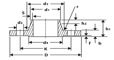
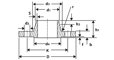
| DIN 2627 PN 400 (in mm) | ||||||||||||||
| Nominal Pipe Size | Diameter at weld Bevel | Flange Dia | Thk of Flange | Dia of Bolt Circle | Length Through Hub | Dia of Hub | Wall Thk | Radius of Hub | Straight Portion | Dia of R/F | Thk of R/F | No. of | Dia of Bolt Holes | |
| DN | D1 | D | B | K | H1 | D3 | S | R | H2 | D4 | F | holes | D2 | KG |
| 10 | 17.20 | 125 | 28 | 85 | 65 | 48 | 3.60 | 4 | 8 | 40 | 2 | 4 | 18 | 2.50 |
| 15 | 26.90 | 145 | 30 | 100 | 68 | 56 | 5.00 | 4 | 8 | 45 | 2 | 4 | 22 | 3.57 |
| 25 | 42.40 | 180 | 38 | 130 | 90 | 82 | 7.10 | 4 | 10 | 68 | 2 | 4 | 26 | 7.35 |
| 40 | 60.30 | 220 | 48 | 165 | 110 | 106 | 10.00 | 6 | 12 | 88 | 3 | 4 | 30 | 13.93 |
| 50 | 76.10 | 235 | 52 | 180 | 120 | 120 | 12.50 | 6 | 15 | 102 | 3 | 8 | 30 | 16.50 |
| 65 | 101.60 | 290 | 64 | 225 | 135 | 158 | 16.00 | 6 | 18 | 122 | 3 | 8 | 33 | 31.33 |
| 80 | 114.30 | 305 | 68 | 240 | 150 | 174 | 17.50 | 8 | 20 | 138 | 3 | 8 | 33 | 37.99 |
| 100 | 139.70 | 370 | 80 | 295 | 175 | 215 | 22.20 | 8 | 25 | 162 | 3 | 8 | 39 | 66.77 |
| 125 | 193.70 | 415 | 92 | 340 | 200 | 258 | 30.00 | 8 | 30 | 188 | 3 | 12 | 39 | 94.73 |
| 150 | 219.10 | 475 | 105 | 390 | 225 | 302 | 35.00 | 10 | 35 | 218 | 3 | 12 | 42 | 144.85 |
| 200 | 273.00 | 585 | 130 | 490 | 280 | 388 | 40.00 | 10 | 40 | 285 | 3 | 16 | 48 | 269.50 |

| DIN 2628 PN 250 (in mm) | ||||||||||||||
| Nominal Pipe Size | Diameter at weld Bevel | Flange Dia | Thk of Flange | Dia of Bolt Circle | Length Through Hub | Dia of Hub | Wall Thk | Radius of Hub | Straight Portion | Dia of R/F | Thk of R/F | No. of | Dia of Bolt Holes | |
| DN | D1 | D | B | K | H1 | D3 | S | R | H2 | D4 | F | holes | D2 | KG |
| 10 | 17.2 | 125 | 24 | 85 | 58 | 44 | 2.6 | 4 | 6 | 40 | 2 | 4 | 18 | 2.09 |
| 15 | 21.3 | 130 | 26 | 90 | 60 | 48 | 2.6 | 4 | 6 | 45 | 2 | 4 | 18 | 2.47 |
| 25 | 33.7 | 150 | 28 | 105 | 65 | 60 | 3.6 | 4 | 8 | 68 | 2 | 4 | 22 | 3.53 |
| 40 | 48.3 | 185 | 34 | 135 | 80 | 84 | 5 | 6 | 10 | 88 | 3 | 4 | 26 | 6.58 |
| 50 | 60.3 | 200 | 38 | 150 | 85 | 95 | 6.3 | 6 | 10 | 102 | 3 | 8 | 26 | 8.09 |
| 65 | 76.1 | 230 | 42 | 180 | 95 | 124 | 8 | 6 | 12 | 122 | 3 | 8 | 26 | 12.59 |
| 80 | 101.6 | 255 | 46 | 200 | 102 | 136 | 11 | 8 | 12 | 138 | 3 | 8 | 30 | 16.32 |
| 100 | 127 | 300 | 54 | 235 | 120 | 164 | 14.2 | 8 | 14 | 162 | 3 | 8 | 33 | 27.07 |
| 125 | 152.4 | 340 | 60 | 275 | 140 | 200 | 16 | 8 | 16 | 188 | 3 | 12 | 33 | 38.79 |
| 150 | 177.8 | 390 | 68 | 320 | 160 | 240 | 17.5 | 10 | 18 | 218 | 3 | 12 | 36 | 59.05 |
| 200 | 244.5 | 485 | 82 | 400 | 190 | 305 | 25 | 10 | 25 | 285 | 3 | 12 | 42 | 109.45 |
| 250 | 298.5 | 585 | 100 | 490 | 215 | 385 | 32 | 12 | 30 | 345 | 3 | 16 | 48 | 189.94 |

| DIN 2629 P N 320 (in mm) | ||||||||||||||
| Nominal Pipe Size | Diameter at weld Bevel | Flange Dia | Thk of Flange | Dia of Bolt Circle | Length Through Hub | Dia of Hub | Wall Thk | Radius of Hub | Straight Portion | Dia of R/F | Thk of R/F | No. of | Dia of Bolt Holes | |
| DN | D1 | D | B | K | H1 | D3 | S | R | H2 | D4 | F | holes | D2 | KG |
| 10 | 17.2 | 125 | 24 | 85 | 58 | 44 | 2.6 | 4 | 6 | 40 | 2 | 4 | 18 | 2.09 |
| 15 | 21.3 | 130 | 26 | 90 | 60 | 48 | 3.2 | 4 | 6 | 45 | 2 | 4 | 18 | 2.49 |
| 25 | 33.7 | 160 | 34 | 115 | 78 | 68 | 5 | 4 | 8 | 68 | 2 | 4 | 22 | 5.11 |
| 40 | 48.3 | 195 | 38 | 145 | 88 | 92 | 6.3 | 6 | 10 | 88 | 3 | 4 | 26 | 8.47 |
| 50 | 63.5 | 210 | 42 | 160 | 100 | 106 | 8 | 6 | 10 | 102 | 3 | 8 | 26 | 10.52 |
| 65 | 88.9 | 255 | 51 | 200 | 120 | 138 | 11 | 6 | 12 | 122 | 3 | 8 | 30 | 19.26 |
| 80 | 101.6 | 275 | 55 | 220 | 130 | 156 | 12.5 | 8 | 14 | 138 | 3 | 8 | 30 | 24.81 |
| 100 | 133 | 335 | 65 | 265 | 145 | 186 | 16 | 8 | 16 | 162 | 3 | 8 | 36 | 42.18 |
| 125 | 168.3 | 380 | 75 | 310 | 175 | 230 | 20 | 8 | 20 | 188 | 3 | 12 | 36 | 63.30 |
| 150 | 193.7 | 425 | 84 | 350 | 195 | 265 | 25 | 10 | 25 | 218 | 3 | 12 | 36 | 91.04 |
| 175 | 219.1 | 485 | 95 | 400 | 215 | 308 | 28 | 10 | 28 | 260 | 3 | 12 | 42 | 135.46 |
| 200 | 244.5 | 525 | 103 | 440 | 235 | 345 | 30 | 10 | 30 | 285 | 3 | 16 | 42 | 170.94 |
| 250 | 323.9 | 640 | 125 | 540 | 300 | 428 | 40 | 12 | 40 | 345 | 3 | 16 | 52 | 311.99 |

| DIN 2630 P N 2.5 (in mm) | ||||||||||||||
| Nominal Pipe Size | Diameter at weld Bevel | Flange Dia | Thk of Flange | Dia of Bolt Circle | Length Through Hub | Dia of Hub | Wall Thk | Radius of Hub | Straight Portion | Dia of R/F | Thk of R/F | No. of | Dia of Bolt Holes | |
| DN | D1 | D | B | K | H1 | D3 | S | R | H2 | D4 | F | holes | D2 | KG |
| 10 | 17.20 | 75 | 12 | 50 | 28 | 26 | 1.8 | 4 | 6 | 35 | 2 | 4 | 11 | 0.34 |
| 15 | 21.30 | 80 | 12 | 55 | 30 | 30 | 2 | 4 | 6 | 40 | 2 | 4 | 11 | 0.46 |
| 20 | 26.90 | 90 | 14 | 65 | 32 | 38 | 2.3 | 4 | 6 | 50 | 2 | 4 | 11 | 0.60 |
| 25 | 33.70 | 100 | 14 | 75 | 35 | 42 | 2.6 | 4 | 6 | 60 | 2 | 4 | 11 | 0.78 |
| 32 | 42.40 | 120 | 14 | 90 | 35 | 55 | 2.6 | 6 | 6 | 70 | 2 | 4 | 14 | 1.06 |
| 40 | 48.30 | 130 | 14 | 100 | 38 | 62 | 2.6 | 6 | 7 | 80 | 3 | 4 | 14 | 1.20 |
| 50 | 60.30 | 140 | 14 | 110 | 38 | 74 | 2.9 | 6 | 8 | 90 | 3 | 4 | 14 | 1.36 |
| 65 | 76.10 | 160 | 14 | 130 | 38 | 88 | 2.9 | 6 | 9 | 110 | 3 | 4 | 14 | 1.60 |
| 80 | 88.90 | 190 | 16 | 150 | 42 | 102 | 3.2 | 8 | 10 | 128 | 3 | 4 | 18 | 2.72 |
| 100 | 114.30 | 210 | 16 | 170 | 45 | 130 | 3.6 | 8 | 10 | 148 | 3 | 4 | 18 | 3.22 |
| 125 | 139.70 | 240 | 18 | 200 | 48 | 155 | 4 | 8 | 10 | 178 | 3 | 8 | 18 | 4.42 |
| 150 | 168.3 | 265 | 18 | 225 | 48 | 184 | 4.5 | 10 | 12 | 202 | 3 | 8 | 18 | 5.04 |
| 200 | 219.10 | 320 | 20 | 280 | 55 | 236 | 5.9 | 10 | 15 | 258 | 3 | 8 | 18 | 7.95 |
| 250 | 273.00 | 375 | 22 | 335 | 60 | 290 | 6.3 | 12 | 16 | 312 | 3 | 12 | 18 | 10.57 |
| 300 | 323.90 | 440 | 22 | 395 | 62 | 342 | 7.1 | 12 | 15 | 365 | 4 | 12 | 22 | 14.26 |
| 350 | 355.60 | 490 | 22 | 445 | 62 | 385 | 7.1 | 12 | 15 | 415 | 4 | 12 | 22 | 18.56 |
| 400 | 406.40 | 540 | 22 | 495 | 65 | 438 | 7.1 | 12 | 15 | 465 | 4 | 16 | 22 | 21.25 |
| 500 | 506.00 | 645 | 24 | 600 | 68 | 538 | 7.1 | 12 | 15 | 570 | 4 | 20 | 22 | 23.57 |
| 600 | 610.00 | 755 | 24 | 705 | 70 | 640 | 7.1 | 12 | 16 | 670 | 5 | 20 | 26 | 34.50 |
| 700 | 711.00 | 660 | 24 | 810 | 70 | 740 | 7.1 | 12 | 16 | 775 | 5 | 24 | 26 | 40.00 |
| 800 | 813.00 | 975 | 24 | 920 | 70 | 842 | 7.1 | 12 | 16 | 880 | 5 | 24 | 30 | 48.18 |
| 900 | 914.00 | 1075 | 26 | 1020 | 70 | 942 | 7.1 | 12 | 16 | 980 | 5 | 24 | 30 | 58.10 |
| 1000 | 1016.00 | 1175 | 26 | 1120 | 70 | 1045 | 7.1 | 16 | 16 | 1080 | 5 | 25 | 30 | 63.41 |
| 1200 | 1220.00 | 1375 | 26 | 1320 | 70 | 1245 | 7 | 16 | 16 | 1280 | 5 | 32 | 30 | 72.82 |
| 1400 | 1420.00 | 1575 | 26 | 1520 | 70 | 1445 | 7 | 16 | 16 | 1480 | 5 | 36 | 30 | 84.50 |
| 1600 | 1620.00 | 1790 | 26 | 1730 | 80 | 1645 | 8 | 16 | 20 | 1680 | 5 | 40 | 30 | 111.57 |
| 1800 | 1820.00 | 1990 | 26 | 1930 | 80 | 1845 | 9 | 16 | 20 | 1890 | 5 | 44 | 30 | 128.41 |
| 2000 | 2020.00 | 2190 | 26 | 2130 | 80 | 2045 | 10 | 18 | 22 | 2090 | 5 | 48 | 30 | 145.00 |
| 2200 | 2220.00 | 2405 | 28 | 2340 | 90 | 2248 | 10 | 18 | 25 | 2295 | 6 | 52 | 33 | 184.10 |
| 2400 | 2420.00 | 2605 | 28 | 2540 | 90 | 2448 | 10 | 18 | 25 | 2495 | 6 | 56 | 32 | 200.47 |
| 2600 | 2620.00 | 2805 | 28 | 2740 | 90 | 2648 | 10 | 18 | 25 | 2695 | 6 | 60 | 33 | 216.00 |
| 2800 | 2820.00 | 3030 | 30 | 2960 | 90 | 2848 | 10 | 18 | 25 | 2910 | 6 | 64 | 36 | 268.05 |
| 3000 | 3020.00 | 3230 | 30 | 3160 | 90 | 3050 | 10 | 18 | 25 | 3110 | 6 | 66 | 36 | 285.00 |
| 3200 | 3220.00 | 3430 | 30 | 3350 | 90 | 3250 | 10 | 20 | 25 | 3310 | 6 | 72 | 36 | 306.75 |
| 3400 | 3420.00 | 3630 | 32 | 3560 | 95 | 3450 | 10 | 20 | 28 | 3510 | 6 | 76 | 36 | 346.71 |
| 3600 | 3620.00 | 3340 | 32 | 3770 | 100 | 3652 | 10 | 20 | 28 | 3720 | 6 | 80 | 36 | 305.71 |
| 3800 | 3820.00 | 4045 | 34 | 3970 | 100 | 3852 | 10 | 20 | 28 | 3920 | 6 | 80 | - | - |
| 4000 | 4020.00 | 4245 | 34 | 4170 | 100 | 4052 | 10 | 20 | 28 | 4120 | 6 | 84 | - | - |

| DIN 2631 PN 6 (in mm) | ||||||||||||||
| Nominal Pipe Size | Diameter at weld Bevel | Flange Dia | Thk of Flange | Dia of Bolt Circle | Length Through Hub | Dia of Hub | Wall Thk | Radius of Hub | Straight Portion | Dia of R/F | Thk of R/F | No. of | Dia of Bolt Holes | |
| DN | D1 | D | B | K | H1 | D3 | S | R | H2 | D4 | F | holes | D2 | KG |
| 10 | 17.20 | 75 | 12 | 50 | 28 | 26 | 1.8 | 4 | 6 | 35 | 2 | 4 | 11 | 0.34 |
| 15 | 21.30 | 80 | 12 | 55 | 30 | 30 | 2 | 4 | 6 | 40 | 2 | 4 | 11 | 0.40 |
| 20 | 26.90 | 90 | 14 | 65 | 32 | 38 | 2.3 | 4 | 6 | 50 | 2 | 4 | 11 | 0.60 |
| 25 | 33.70 | 100 | 14 | 75 | 35 | 42 | 2.6 | 4 | 6 | 60 | 2 | 4 | 11 | 0.75 |
| 32 | 42.40 | 120 | 14 | 90 | 35 | 55 | 2.6 | 6 | 6 | 70 | 2 | 4 | 14 | 1.06 |
| 40 | 48.30 | 130 | 14 | 100 | 38 | 62 | 2.6 | 6 | 7 | 80 | 3 | 4 | 14 | 1.20 |
| 50 | 60.30 | 140 | 14 | 110 | 38 | 74 | 2.9 | 6 | 8 | 90 | 3 | 4 | 14 | 1.36 |
| 65 | 76.10 | 160 | 14 | 130 | 38 | 88 | 2.9 | 6 | 9 | 110 | 3 | 4 | 14 | 1.69 |
| 80 | 88.90 | 190 | 16 | 150 | 42 | 102 | 3.2 | 8 | 10 | 128 | 3 | 4 | 18 | 2.72 |
| 100 | 114.30 | 210 | 16 | 170 | 45 | 130 | 3.6 | 8 | 10 | 148 | 3 | 4 | 18 | 3.22 |
| 125 | 139.70 | 240 | 18 | 200 | 48 | 155 | 4 | 8 | 10 | 178 | 3 | 8 | 18 | 4.42 |
| 150 | 168 | 265 | 18 | 225 | 48 | 184 | 4.5 | 10 | 12 | 202 | 3 | 8 | 18 | 5.04 |
| 200 | 219.10 | 320 | 20 | 280 | 55 | 236 | 5.9 | 10 | 15 | 258 | 3 | 8 | 18 | 7.95 |
| 250 | 273.00 | 375 | 22 | 335 | 60 | 290 | 6.3 | 12 | 15 | 312 | 3 | 12 | 18 | 10.87 |
| 300 | 323.90 | 440 | 22 | 395 | 62 | 342 | 7.1 | 12 | 15 | 365 | 4 | 12 | 22 | 14.26 |
| 350 | 355.60 | 490 | 22 | 445 | 62 | 385 | 7.1 | 12 | 15 | 415 | 4 | 12 | 22 | 16.78 |
| 400 | 406.60 | 540 | 22 | 495 | 65 | 438 | 7.1 | 12 | 15 | 465 | 4 | 16 | 22 | 19.10 |
| 500 | 508.00 | 645 | 24 | 600 | 68 | 538 | 7.1 | 12 | 15 | 570 | 4 | 20 | 22 | 28.67 |
| 600 | 610.00 | 755 | 24 | 705 | 70 | 640 | 7.1 | 12 | 16 | 670 | 5 | 20 | 26 | 34.80 |
| 700 | 711.00 | 860 | 24 | 810 | 70 | 740 | 7.1 | 12 | 16 | 775 | 5 | 24 | 26 | 40.94 |
| 800 | 813.00 | 975 | 24 | 920 | 70 | 842 | 7.1 | 12 | 16 | 880 | 5 | 24 | 30 | 49.19 |
| 900 | 914.00 | 1075 | 26 | 1020 | 70 | 942 | 7.1 | 12 | 16 | 980 | 5 | 24 | 30 | 58.10 |
| 1000 | 1016.00 | 1175 | 26 | 1120 | 70 | 1045 | 7.1 | 16 | 16 | 1080 | 5 | 28 | 30 | 63.48 |
| 1200 | 1220.00 | 1405 | 28 | 1340 | 90 | 1248 | 8 | 16 | 20 | 1295 | 5 | 32 | 33 | 100.17 |
| 1400 | 1420.00 | 1630 | 32 | 1560 | 90 | 1452 | 8 | 16 | 20 | 1510 | 5 | 36 | 36 | 142.78 |
| 1600 | 1620.00 | 1830 | 34 | 1760 | 90 | 1655 | 9 | 16 | 20 | 1710 | 5 | 40 | 36 | 174.36 |
| 1800 | 1820.00 | 2045 | 36 | 1970 | 100 | 1855 | 10 | 16 | 20 | 1920 | 5 | 44 | 39 | 226.98 |
| 2000 | 2020.00 | 2265 | 38 | 2180 | 110 | 2058 | 11 | 16 | 25 | 2125 | 5 | 48 | 42 | 292.12 |
| 2200 | 2220.00 | 2475 | 42 | 2390 | 115 | 2260 | 12 | 18 | 25 | 2335 | 6 | 52 | 42 | 366.33 |
| 2400 | 2420.00 | 2685 | 44 | 2600 | 125 | 2462 | 13 | 18 | 25 | 2545 | 6 | 56 | 42 | 448.52 |
| 2600 | 2620.00 | 2905 | 46 | 2810 | 130 | 2665 | 14 | 18 | 25 | 2750 | 6 | 60 | 48 | 540.16 |
| 2800 | 2820.00 | 3115 | 48 | 3020 | 135 | 2865 | 15 | 18 | 30 | 2960 | 6 | 64 | 48 | 630.03 |
| 3000 | 3020.00 | 3315 | 50 | 3220 | 140 | 3068 | 16 | 18 | 30 | 3160 | 6 | 68 | 48 | 716.33 |
| 3200 | 3220.00 | 3525 | 54 | 3430 | 150 | 3272 | 16 | 20 | 30 | 3370 | 6 | 72 | 48 | 854.42 |
| 3400 | 3420.00 | 3735 | 46 | 3640 | 160 | 3475 | 18 | 20 | 35 | 3580 | 6 | 76 | 48 | 887.81 |
| 3600 | 3620.00 | 3970 | 60 | 3860 | 165 | 3678 | 18 | 20 | 35 | 3790 | 6 | 80 | 56 | 1202.43 |

| DIN 2632 PN 10 (in mm) | ||||||||||||||
| Nominal Pipe Size | Diameter at weld Bevel | Flange Dia | Thk of Flange | Dia of Bolt Circle | Length Through Hub | Dia of Hub | Wall Thk | Radius of Hub | Straight Portion | Dia of R/F | Thk of R/F | No. of | Dia of Bolt Holes | |
| DN | D1 | D | B | K | H1 | D3 | S | R | H2 | D4 | F | holes | D2 | KG |
| 10 | 17.2 | 90 | 14 | 60 | 35 | 28 | 1.8 | 4 | 6 | 40 | 2 | 4 | 14 | 0.58 |
| 15 | 21.3 | 95 | 14 | 65 | 35 | 32 | 2.0 | 4 | 6 | 45 | 2 | 4 | 14 | 0.65 |
| 20 | 26.9 | 105 | 16 | 75 | 38 | 40 | 2.3 | 4 | 6 | 58 | 2 | 4 | 14 | 0.95 |
| 25 | 33.7 | 115 | 16 | 85 | 38 | 45 | 2.6 | 4 | 6 | 68 | 2 | 4 | 14 | 1.14 |
| 32 | 42.4 | 140 | 16 | 100 | 40 | 55 | 2.6 | 6 | 6 | 78 | 2 | 4 | 18 | 1.65 |
| 40 | 48.3 | 150 | 16 | 110 | 42 | 64 | 2.6 | 6 | 7 | 88 | 3 | 4 | 18 | 1.83 |
| 50 | 60.3 | 165 | 18 | 125 | 45 | 75 | 2.9 | 6 | 8 | 102 | 3 | 4 | 18 | 2.48 |
| 65 | 76.1 | 165 | 18 | 145 | 45 | 90 | 2.9 | 6 | 10 | 122 | 3 | 4 | 18 | 3.03 |
| 80 | 88.9 | 200 | 20 | 160 | 50 | 105 | 3.2 | 6 | 10 | 138 | 3 | 8 | 18 | 3.82 |
| 100 | 114.3 | 220 | 20 | 180 | 52 | 131 | 3.6 | 8 | 12 | 158 | 3 | 8 | 18 | 4.41 |
| 125 | 139.7 | 250 | 22 | 210 | 55 | 156 | 4.0 | 8 | 12 | 188 | 3 | 8 | 18 | 6.07 |
| 150 | 168.3 | 285 | 22 | 240 | 55 | 184 | 4.5 | 10 | 12 | 212 | 3 | 8 | 22 | 7.40 |
| 200 | 219.1 | 340 | 24 | 295 | 62 | 235 | 5.9 | 10 | 16 | 268 | 3 | 8 | 22 | 11.10 |
| 250 | 273.0 | 395 | 26 | 350 | 68 | 292 | 6.3 | 12 | 16 | 320 | 3 | 12 | 22 | 14.92 |
| 300 | 323.9 | 445 | 26 | 400 | 68 | 344 | 7.1 | 12 | 16 | 370 | 4 | 12 | 22 | 17.47 |
| 350 | 355.6 | 505 | 26 | 460 | 66 | 385 | 7.1 | 12 | 16 | 430 | 4 | 16 | 22 | 23.70 |
| 400 | 406.4 | 565 | 26 | 515 | 72 | 440 | 7.1 | 12 | 16 | 482 | 4 | 16 | 26 | 28.72 |
| 450 | 457.2 | 615 | 26 | 565 | 72 | 478 | 7.1 | 12 | 16 | 532 | 4 | 20 | 26 | 30.40 |
| 500 | 508.0 | 670 | 28 | 620 | 75 | 542 | 7.1 | 12 | 16 | 585 | 4 | 20 | 26 | 38.27 |
| 600 | 610.0 | 780 | 28 | 725 | 80 | 642 | 7.1 | 12 | 18 | 685 | 5 | 20 | 30 | 46.56 |
| 700 | 711.0 | 895 | 30 | 840 | 80 | 745 | 8.0 | 12 | 18 | 800 | 5 | 24 | 30 | 62.30 |
| 800 | 813.0 | 1015 | 32 | 950 | 90 | 850 | 8.0 | 12 | 18 | 905 | 5 | 24 | 33 | 83.81 |
| 900 | 914.0 | 1115 | 34 | 1050 | 95 | 950 | 10.0 | 12 | 20 | 1005 | 5 | 28 | 33 | 102.45 |
| 1000 | 1016.0 | 1230 | 34 | 1160 | 95 | 1052 | 10.0 | 16 | 20 | 1110 | 5 | 28 | 36 | 118.53 |
| 1200 | 1220.0 | 1455 | 36 | 1380 | 115 | 1255 | 11.0 | 16 | 25 | 1330 | 5 | 32 | 39 | 178.18 |
| 1400 | 1420.0 | 1675 | 42 | 1590 | 120 | 1460 | 12.0 | 16 | 25 | 1535 | 5 | 36 | 42 | 244.75 |
| 1600 | 1620.0 | 1915 | 46 | 1820 | 130 | 1665 | 14.0 | 16 | 25 | 1760 | 5 | 40 | 48 | 353.74 |
| 1800 | 1820.0 | 2115 | 50 | 2020 | 140 | 1868 | 15.0 | 16 | 30 | 1960 | 5 | 44 | 48 | 436.33 |
| 2000 | 2020.0 | 2325 | 54 | 2230 | 150 | 2072 | 16.0 | 16 | 30 | 2170 | 5 | 46 | 48 | 548.04 |
| 2200 | 2220.0 | 2550 | 58 | 2440 | 160 | 2275 | 18.0 | 18 | 35 | 2370 | 5 | 52 | 56 | 685.10 |
| 2400 | 2420.0 | 2760 | 62 | 2650 | 170 | 2478 | 20.0 | 18 | 35 | 2570 | 5 | 56 | 56 | 640.04 |
| 2600 | 2620.0 | 2860 | 66 | 2850 | 180 | 2690 | 22.0 | 18 | 40 | 2780 | 6 | 60 | 56 | 990.16 |
| 2800 | 2820.0 | 3180 | 70 | 3070 | 190 | 2882 | 22.0 | 18 | 40 | 3000 | 6 | 64 | 56 | 1187.16 |
| 3000 | 3020.0 | 3405 | 75 | 3290 | 200 | 3085 | 24.0 | 18 | 45 | 3210 | 6 | 65 | 62 | 1437.06 |
| DIN 2633 PN16 (in mm) | ||||||||||||||
| Nominal Pipe Size | Diameter at weld Bevel | Flange Dia | Thk of Flange | Dia of Bolt Circle | Length Through Hub | Dia of Hub | Wall Thk | Radius of Hub | Straight Portion | Dia of R/F | Thk of R/F | No. of | Dia of Bolt Holes | |
| DN | D1 | D | B | K | H1 | D3 | S | R | H2 | D4 | F | holes | D2 | KG |
| 10 | 17.2 | 90 | 14 | 60 | 35 | 28 | 1.8 | 4 | 6 | 40 | 2 | 4 | 14 | 0.58 |
| 15 | 21.3 | 95 | 14 | 65 | 35 | 32 | 2.0 | 4 | 6 | 45 | 2 | 4 | 14 | 0.65 |
| 20 | 26.9 | 105 | 16 | 75 | 38 | 40 | 2.3 | 4 | 6 | 58 | 2 | 4 | 14 | 0.95 |
| 25 | 33.7 | 115 | 16 | 85 | 38 | 45 | 2.6 | 4 | 6 | 68 | 2 | 4 | 14 | 1.14 |
| 32 | 42.4 | 140 | 16 | 100 | 40 | 56 | 2.6 | 6 | 6 | 78 | 2 | 4 | 18 | 1.65 |
| 40 | 48.3 | 150 | 16 | 110 | 42 | 64 | 2.6 | 6 | 7 | 88 | 3 | 4 | 18 | 1.83 |
| 50 | 60.3 | 165 | 18 | 125 | 45 | 75 | 2.9 | 6 | 8 | 102 | 3 | 4 | 18 | 2.48 |
| 65 | 76.1 | 185 | 18 | 145 | 45 | 90 | 2.9 | 6 | 10 | 122 | 3 | 4 | 18 | 3.03 |
| 80 | 88.9 | 200 | 20 | 160 | 50 | 105 | 3.2 | 8 | 10 | 138 | 3 | 8 | 18 | 3.82 |
| 100 | 114.3 | 220 | 20 | 180 | 52 | 131 | 3.6 | 8 | 12 | 158 | 3 | 8 | 18 | 4.41 |
| 125 | 139.7 | 250 | 22 | 210 | 55 | 156 | 4.0 | 8 | 12 | 188 | 3 | 8 | 18 | 6.07 |
| 150 | 168.3 | 285 | 22 | 240 | 55 | 184 | 4.5 | 10 | 12 | 212 | 3 | 8 | 22 | 7.40 |
| 175 | 193.7 | 315 | 24 | 270 | 60 | 210 | 5.4 | 10 | 12 | 242 | 3 | 8 | 22 | 9.86 |
| 200 | 219.1 | 340 | 24 | 295 | 62 | 235 | 5.9 | 10 | 16 | 268 | 3 | 12 | 22 | 10.85 |
| 250 | 273.0 | 405 | 26 | 355 | 70 | 292 | 6.3 | 12 | 16 | 320 | 3 | 12 | 26 | 15.87 |
| 300 | 323.9 | 460 | 28 | 410 | 78 | 344 | 7.1 | 12 | 16 | 378 | 4 | 12 | 26 | 21.24 |
| 350 | 355.6 | 520 | 30 | 470 | 82 | 390 | 8.0 | 12 | 16 | 438 | 4 | 16 | 26 | 31.38 |
| 400 | 406.4 | 580 | 32 | 525 | 85 | 445 | 8.0 | 12 | 16 | 490 | 4 | 16 | 30 | 39.30 |
| 500 | 508.0 | 715 | 34 | 650 | 90 | 548 | 8.0 | 12 | 16 | 610 | 4 | 20 | 33 | 59.63 |
| 600 | 610.0 | 840 | 36 | 770 | 95 | 652 | 8.8 | 12 | 18 | 725 | 5 | 20 | 36 | 82.54 |
| 700 | 711.0 | 910 | 36 | 840 | 100 | 755 | 8.8 | 12 | 18 | 795 | 5 | 24 | 36 | 83.90 |
| 800 | 813.0 | 1025 | 38 | 950 | 105 | 855 | 10.0 | 12 | 20 | 900 | 5 | 24 | 39 | 107.30 |
| 900 | 914.0 | 1125 | 40 | 1050 | 110 | 955 | 10.0 | 12 | 20 | 1000 | 5 | 28 | 39 | 124.97 |
| 1000 | 1016.0 | 1255 | 42 | 1170 | 120 | 1058 | 10.0 | 16 | 22 | 1115 | 5 | 28 | 42 | 163.76 |
| 1200 | 1220.0 | 1485 | 48 | 1390 | 130 | 1262 | 12.5 | 16 | 30 | 1330 | 5 | 32 | 48 | 244.15 |
| 1400 | 1420.0 | 1685 | 52 | 1590 | 145 | 1465 | 14.2 | 16 | 30 | 1530 | 5 | 36 | 48 | 320.87 |
| 1600 | 1620.0 | 1930 | 58 | 1820 | 160 | 1668 | 16.0 | 16 | 35 | 1750 | 5 | 40 | 56 | 465.83 |
| 1800 | 1820.0 | 2130 | 62 | 2020 | 170 | 1870 | 17.5 | 16 | 35 | 1950 | 5 | 44 | 56 | 570.52 |
| 2000 | 2020.0 | 2345 | 66 | 2230 | 180 | 2072 | 20.0 | 16 | 40 | 2150 | 5 | 48 | 62 | 706.74 |

| DIN 2634 PN 25 (in mm) | ||||||||||||||
| Nominal Pipe Size | Diameter at weld Bevel | Flange Dia | Thk of Flange | Dia of Bolt Circle | Length Through Hub | Dia of Hub | Wall Thk | Radius of Hub | Straight Portion | Dia of R/F | Thk of R/F | No. of | Dia of Bolt Holes | |
| DN | D1 | D | B | K | q | D3 | S | R | H2 | D4 | F | holes | D2 | KG |
| 10 | 17.2 | 90 | 16 | 60 | 35 | 28 | 1.8 | 4 | 6 | 40 | 2 | 4 | 14 | 0.66 |
| 15 | 21.3 | 95 | 16 | 65 | 38 | 32 | 2.0 | 4 | 6 | 45 | 2 | 4 | 14 | 0.75 |
| 20 | 26.9 | 105 | 18 | 75 | 40 | 40 | 2.3 | 4 | 6 | 58 | 2 | 4 | 14 | 1.07 |
| 25 | 33.7 | 115 | 18 | 85 | 40 | 46 | 2.6 | 4 | 6 | 68 | 2 | 4 | 14 | 1.28 |
| 32 | 42.4 | 140 | 18 | 100 | 42 | 56 | 2.6 | 6 | 6 | 78 | 2 | 4 | 18 | 1.86 |
| 40 | 48.3 | 150 | 18 | 110 | 45 | 64 | 2.6 | 6 | 7 | 88 | 3 | 4 | 18 | 2.08 |
| 50 | 60.3 | 165 | 20 | 125 | 48 | 75 | 2.9 | 6 | 8 | 102 | 3 | 4 | 18 | 2.78 |
| 65 | 76.1 | 185 | 22 | 145 | 52 | 90 | 2.9 | 6 | 10 | 122 | 3 | 8 | 18 | 3.61 |
| 80 | 88.9 | 200 | 24 | 160 | 58 | 105 | 3.2 | 8 | 12 | 138 | 3 | 8 | 18 | 4.62 |
| 100 | 114.3 | 235 | 24 | 190 | 65 | 134 | 3.6 | 8 | 12 | 162 | 3 | 8 | 22 | 6.27 |
| 125 | 139.7 | 270 | 26 | 220 | 68 | 162 | 4.0 | 8 | 12 | 188 | 3 | 8 | 26 | 8.61 |
| 150 | 166.3 | 300 | 28 | 250 | 75 | 192 | 4.5 | 10 | 12 | 218 | 3 | 8 | 26 | 11.29 |
| 175 | 193.7 | 330 | 28 | 280 | 75 | 218 | 5.6 | 10 | 15 | 248 | 3 | 12 | 26 | 13.11 |
| 200 | 219.1 | 360 | 30 | 310 | 80 | 244 | 6.3 | 10 | 16 | 278 | 3 | 12 | 26 | 16.61 |
| 250 | 273.0 | 425 | 32 | 370 | 88 | 298 | 7.1 | 12 | 18 | 335 | 3 | 12 | 30 | 23.48 |
| 300 | 323.9 | 485 | 34 | 430 | 92 | 352 | 8.0 | 12 | 18 | 395 | 4 | 16 | 30 | 30.74 |
| 350 | 355.6 | 555 | 38 | 490 | 100 | 398 | 8.0 | 12 | 20 | 450 | 4 | 16 | 33 | 47.20 |
| 400 | 406.4 | 620 | 40 | 550 | 110 | 452 | 8.8 | 12 | 20 | 505 | 4 | 16 | 36 | 61.69 |
| 500 | 508.0 | 730 | 44 | 660 | 125 | 558 | 10.0 | 12 | 20 | 615 | 4 | 20 | 36 | 89.57 |
| 600 | 610.0 | 845 | 46 | 770 | 125 | 660 | 11.0 | 12 | 20 | 720 | 5 | 20 | 39 | 114.96 |
| 700 | 711.0 | 960 | 46 | 875 | 125 | 760 | 12.5 | 12 | 20 | 820 | 5 | 24 | 42 | 139.50 |
| 800 | 813.0 | 1085 | 50 | 990 | 135 | 865 | 14.2 | 12 | 22 | 930 | 5 | 24 | 48 | 188.71 |
| 900 | 914.0 | 1185 | 54 | 1090 | 145 | 968 | 16.0 | 12 | 24 | 1030 | 5 | 28 | 48 | 231.48 |
| 1000 | 1016.0 | 1320 | 58 | 1210 | 155 | 1070 | 17.5 | 16 | 24 | 1140 | 5 | 28 | 56 | 303.52 |
| DIN 2635 PN 40 (in mm) | ||||||||||||||
| Nominal Pipe Size | Diameter at weld Bevel | Flange Dia | Thk of Flange | Dia of Bolt Circle | Length Through Hub | Dia of Hub | Wall Thk | Radius of Hub | Straight Portion | Dia of R/F | Thk of R/F | No. of | Dia of Bolt Holes | |
| DN | D1 | D | B | K | H1 | D3 | S | R | H2 | D4 | F | holes | D2 | KG |
| 10 | 17.2 | 90 | 16 | 60 | 35 | 28 | 1.8 | 4 | 6 | 40 | 2 | 4 | 14 | 0.66 |
| 15 | 21.3 | 95 | 16 | 65 | 38 | 32 | 2.0 | 4 | 6 | 45 | 2 | 4 | 14 | 0.75 |
| 20 | 26.9 | 105 | 18 | 75 | 40 | 40 | 2.3 | 4 | 6 | 58 | 2 | 4 | 14 | 1.07 |
| 25 | 33.7 | 115 | 18 | 85 | 40 | 46 | 2.6 | 4 | 6 | 68 | 2 | 4 | 14 | 1.28 |
| 32 | 42.4 | 140 | 18 | 100 | 42 | 56 | 2.6 | 6 | 6 | 78 | 2 | 4 | 18 | 1.86 |
| 40 | 48.3 | 150 | 18 | 110 | 45 | 64 | 2.6 | 6 | 7 | 88 | 3 | 4 | 18 | 2.08 |
| 50 | 60.3 | 165 | 20 | 125 | 48 | 75 | 2.9 | 6 | 8 | 102 | 3 | 4 | 18 | 2.78 |
| 65 | 76.1 | 185 | 22 | 145 | 52 | 90 | 2.9 | 6 | 10 | 122 | 3 | 8 | 18 | 3.81 |
| 80 | 88.9 | 200 | 24 | 160 | 58 | 105 | 3.2 | 8 | 12 | 138 | 3 | 8 | 18 | 4.62 |
| 100 | 114.3 | 235 | 24 | 190 | 65 | 134 | 3.6 | 8 | 12 | 162 | 3 | 8 | 22 | 6.27 |
| 125 | 139.7 | 270 | 26 | 220 | 68 | 162 | 4.0 | 8 | 12 | 188 | 3 | 8 | 26 | 8.61 |
| 150 | 168.3 | 300 | 28 | 250 | 75 | 192 | 4.5 | 10 | 12 | 218 | 3 | 8 | 26 | 11.29 |
| 175 | 193.7 | 350 | 32 | 295 | 82 | 218 | 5.6 | 10 | 15 | 260 | 3 | 12 | 30 | 17.01 |
| 200 | 219.1 | 375 | 34 | 320 | 88 | 244 | 6.3 | 10 | 16 | 285 | 3 | 12 | 30 | 20.49 |
| 250 | 273.0 | 450 | 38 | 385 | 105 | 306 | 7.1 | 12 | 18 | 345 | 3 | 12 | 33 | 33.34 |
| 300 | 323.9 | 515 | 42 | 450 | 115 | 362 | 8.0 | 12 | 18 | 410 | 4 | 16 | 33 | 46.55 |
| 350 | 355.6 | 580 | 46 | 510 | 125 | 408 | 8.8 | 12 | 20 | 465 | 4 | 16 | 36 | 67.73 |
| 400 | 406.4 | 660 | 50 | 585 | 135 | 462 | 11.0 | 12 | 20 | 535 | 4 | 16 | 39 | 96.73 |
| 500 | 508.0 | 755 | 52 | 670 | 140 | 562 | 14.2 | 12 | 20 | 615 | 4 | 20 | 42 | 120.96 |
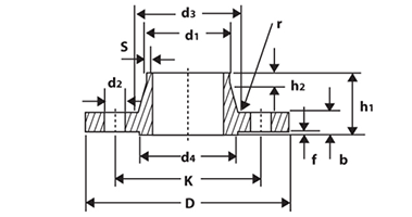
| DIN 2636 PN 64 (in mm) | ||||||||||||||
| Nominal Pipe Size | Diameter at weld Bevel | Flange Dia | Thk of Flange | Dia of Bolt Circle | Length Through Hub | Dia of Hub | Wall Thk | Radius of Hub | Straight Portion | Dia of R/F | Thk of R/F | No. of | Dia of Bolt Holes | |
| DN | D1 | D | B | K | H1 | D3 | S | R | H2 | D4 | F | holes | D2 | KG |
| 10 | 17.2 | 100 | 20 | 70 | 45 | 32 | 1.8 | 4 | 6 | 40 | 2 | 4 | 14 | 1.08 |
| 15 | 21.3 | 105 | 20 | 75 | 45 | 34 | 2.0 | 4 | 6 | 45 | 2 | 4 | 14 | 1.19 |
| 25 | 33.7 | 140 | 24 | 100 | 58 | 52 | 2.6 | 4 | 8 | 68 | 2 | 4 | 18 | 2.60 |
| 40 | 48.3 | 170 | 26 | 125 | 62 | 70 | 2.9 | 6 | 10 | 88 | 3 | 4 | 22 | 3.99 |
| 50 | 60.3 | 180 | 26 | 135 | 62 | 82 | 2.9 | 6 | 10 | 102 | 3 | 4 | 22 | 4.42 |
| 65 | 76.1 | 205 | 26 | 160 | 66 | 98 | 3.2 | 6 | 12 | 122 | 3 | 8 | 22 | 5.49 |
| 80 | 88.9 | 215 | 28 | 170 | 72 | 112 | 3.6 | 8 | 12 | 138 | 3 | 8 | 22 | 6.50 |
| 100 | 114.3 | 250 | 30 | 200 | 76 | 138 | 4.0 | 8 | 12 | 162 | 3 | 8 | 26 | 9.06 |
| 125 | 139.7 | 295 | 34 | 240 | 88 | 168 | 4.5 | 8 | 12 | 188 | 3 | 8 | 30 | 14.23 |
| 150 | 168.3 | 345 | 36 | 280 | 95 | 202 | 5.6 | 10 | 12 | 218 | 3 | 8 | 33 | 20.92 |
| 175 | 193.7 | 375 | 40 | 310 | 105 | 228 | 6.3 | 10 | 16 | 260 | 3 | 12 | 33 | 26.28 |
| 200 | 219.1 | 415 | 42 | 345 | 110 | 256 | 7.1 | 10 | 16 | 285 | 3 | 12 | 36 | 33.56 |
| 250 | 273.0 | 470 | 46 | 400 | 125 | 316 | 8.8 | 12 | 18 | 345 | 3 | 12 | 36 | 47.32 |
| 300 | 323.9 | 530 | 52 | 460 | 140 | 372 | 11.0 | 12 | 18 | 410 | 4 | 16 | 36 | 66.44 |
| 350 | 355.6 | 600 | 56 | 525 | 150 | 420 | 12.5 | 12 | 20 | 465 | 4 | 16 | 39 | 96.23 |
| 400 | 406.4 | 670 | 60 | 585 | 160 | 475 | 14.2 | 12 | 20 | 535 | 4 | 16 | 42 | 127.70 |

| DIN 2637 PN 100 (in mm) | ||||||||||||||
| Nominal Pipe Size | Diameter at weld Bevel | Flange Dia | Thk of Flange | Dia of Bolt Circle | Length Through Hub | Dia of Hub | Wall Thk | Radius of Hub | Straight Portion | Dia of R/F | Thk of R/F | No. of | Dia of Bolt Holes | |
| DN | d1 | D | B | K | H1 | D3 | S | R | H2 | D4 | F | holes | D2 | KG |
| 10 | 17.2 | 100 | 20 | 70 | 45 | 32 | 1.8 | 4 | 6 | 40 | 2 | 4 | 14 | 1.08 |
| 15 | 21.3 | 105 | 20 | 75 | 45 | 34 | 2.0 | 4 | 6 | 45 | 2 | 4 | 14 | 1.19 |
| 25 | 33.7 | 140 | 24 | 100 | 58 | 52 | 2.6 | 4 | 8 | 68 | 2 | 4 | 18 | 2.60 |
| 40 | 48.3 | 170 | 26 | 125 | 62 | 70 | 2.9 | 6 | 10 | 88 | 3 | 4 | 22 | 3.99 |
| 50 | 60.3 | 195 | 28 | 145 | 68 | 90 | 3.2 | 6 | 10 | 102 | 3 | 4 | 26 | 5.70 |
| 65 | 76.1 | 220 | 30 | 170 | 76 | 108 | 3.6 | 6 | 12 | 122 | 3 | 8 | 26 | 7.43 |
| 80 | 88.9 | 230 | 32 | 180 | 78 | 120 | 4.0 | 8 | 12 | 138 | 3 | 8 | 26 | 8.58 |
| 100 | 114.3 | 265 | 36 | 210 | 90 | 150 | 5.0 | 8 | 12 | 162 | 3 | 8 | 30 | 12.79 |
| 125 | 139.7 | 315 | 40 | 250 | 105 | 180 | 6.3 | 8 | 12 | 188 | 3 | 8 | 33 | 20.68 |
| 150 | 168.3 | 355 | 44 | 290 | 115 | 210 | 7.1 | 10 | 12 | 218 | 3 | 12 | 33 | 27.76 |
| 175 | 193.7 | 385 | 48 | 320 | 127 | 245 | 8.8 | 10 | 16 | 260 | 3 | 12 | 33 | 36.94 |
| 200 | 219.1 | 430 | 52 | 360 | 130 | 278 | 10.0 | 10 | 16 | 285 | 3 | 12 | 36 | 49.35 |
| 250 | 273.0 | 505 | 60 | 430 | 157 | 340 | 12.5 | 12 | 18 | 345 | 3 | 12 | 39 | 80.09 |
| 300 | 323.9 | 585 | 68 | 500 | 170 | 400 | 14.2 | 12 | 18 | 410 | 4 | 16 | 42 | 116.25 |
| 350 | 355.6 | 655 | 74 | 560 | 189 | 460 | 16.0 | 12 | 20 | 465 | 4 | 16 | 48 | 166.09 |

| DIN 2638 PN160 (in mm) | ||||||||||||||
| Nominal Pipe Size | Diameter at weld Bevel | Flange Dia | Thk of Flange | Dia of Bolt Circle | Length Through Hub | Dia of Hub | Wall Thk | Radius of Hub | Straight Portion | Dia of R/F | Thk of R/F | No. of | Dia of Bolt Holes | |
| DN | D1 | D | B | K | H1 | D3 | S | R | H2 | D4 | F | holes | D2 | KG |
| 10 | 17.2 | 100 | 20 | 70 | 45 | 32 | 2.0 | 4 | 6 | 40 | 2 | 4 | 14 | 1.08 |
| 15 | 21.3 | 105 | 20 | 75 | 45 | 34 | 2.0 | 4 | 6 | 45 | 2 | 4 | 14 | 1.19 |
| 25 | 33.7 | 140 | 24 | 100 | 58 | 52 | 2.9 | 4 | 8 | 68 | 2 | 4 | 18 | 2.62 |
| 40 | 48.3 | 170 | 28 | 125 | 64 | 70 | 3.6 | 6 | 10 | 88 | 3 | 4 | 22 | 4.34 |
| 50 | 60.3 | 195 | 30 | 145 | 75 | 90 | 4.0 | 6 | 10 | 102 | 3 | 4 | 26 | 6.27 |
| 65 | 76.1 | 220 | 34 | 170 | 82 | 108 | 5.0 | 6 | 12 | 122 | 3 | 8 | 26 | 8.61 |
| 80 | 88.9 | 230 | 36 | 180 | 86 | 120 | 6.3 | 8 | 12 | 138 | 3 | 8 | 26 | 10.09 |
| 100 | 114.3 | 265 | 40 | 210 | 100 | 150 | 8.0 | 8 | 12 | 162 | 3 | 8 | 30 | 15.07 |
| 125 | 139.7 | 315 | 44 | 250 | 115 | 180 | 10.0 | 8 | 14 | 188 | 3 | 8 | 33 | 24.09 |
| 150 | 168.3 | 355 | 50 | 290 | 128 | 210 | 12.5 | 10 | 14 | 218 | 3 | 12 | 33 | 34.02 |
| 175 | 193.7 | 390 | 54 | 320 | 138 | 245 | 14.2 | 10 | 16 | 260 | 3 | 12 | 36 | 44.90 |
| 200 | 219.1 | 490 | 60 | 360 | 140 | 278 | 16.0 | 10 | 16 | 285 | 3 | 12 | 36 | 60.03 |
| 250 | 273.0 | 515 | 68 | 430 | 155 | 340 | 20.0 | 12 | 18 | 345 | 3 | 12 | 42 | 96.52 |
| 300 | 323.9 | 585 | 76 | 500 | 175 | 400 | 22.2 | 12 | 18 | 410 | 4 | 16 | 42 | 138.80 |
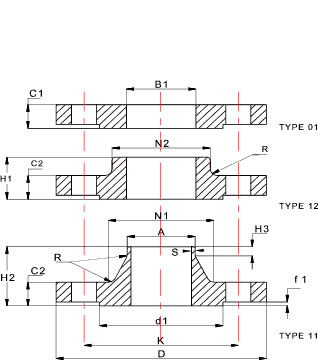
| BS EN 1092-1:2002 PN 16 DIMENSIONS (in mm) | ||||||||||||||||||
| Nominal Pipe Size | Flange Dia | Thk of Flanges | Length Through Hub | Straight Portion of Neck | Radius | Diameter at weld Bevel | Dia of Hub | Bore of S/O | Dia of R/F | Thk of RFD | Thk of Neck | Dia of Bolt Circle | Dia of Bolt Hole | No. of Holes | Size of Bolt | |||
| DN | D | C1 | C2 | H1 | H2 | H3 | R | A | N1 | N2 | B1 | d1 | f1 | S | K | L | No | Size |
| 10 | 90 | 14 | 14 | 20 | 35 | 6 | 4 | 17.2 | 28 | 30 | 18 | 40 | 2 | 1.8 | 60 | 14 | 4 | M12 |
| 15 | 95 | 14 | 14 | 20 | 35 | 6 | 4 | 21.3 | 32 | 35 | 22 | 45 | 2 | 2.0 | 65 | 14 | 4 | M12 |
| 20 | 105 | 14 | 14 | 24 | 38 | 6 | 4 | 26.9 | 39 | 45 | 27.5 | 58 | 2 | 2.3 | 75 | 14 | 4 | M12 |
| 25 | 115 | 16 | 16 | 24 | 38 | 6 | 4 | 33.7 | 46 | 52 | 34.5 | 68 | 2 | 2.6 | 85 | 14 | 4 | M12 |
| 32 | 140 | 18 | 16 | 26 | 40 | 6 | 6 | 42.4 | 56 | 60 | 43.5 | 78 | 2 | 2.6 | 100 | 18 | 4 | M16 |
| 40 | 150 | 18 | 16 | 26 | 42 | 7 | 6 | 48.3 | 64 | 70 | 49.5 | 88 | 2 | 2.6 | 110 | 18 | 4 | M16 |
| 50 | 165 | 19 | 18 | 28 | 45 | 8 | 6 | 60.3 | 75 | 84 | 61.5 | 102 | 2 | 2.9 | 125 | 18 | 4 | M16 |
| 65 | 185 | 20 | 18 | 32 | 45 | 10 | 6 | 76.1 | 90 | 104 | 77.5 | 122 | 2 | 2.9 | 145 | 18 | 8** | M16 |
| 80 | 200 | 20 | 20 | 34 | 50 | 10 | 8 | 88.9 | 105 | 118 | 90.5 | 138 | 2 | 3.2 | 160 | 18 | 8 | M16 |
| 100 | 220 | 22 | 20 | 40 | 52 | 12 | 8 | 114.3 | 131 | 140 | 116 | 158 | 2 | 3.6 | 180 | 18 | 8 | M16 |
| 125 | 250 | 22 | 22 | 44 | 55 | 12 | 8 | 139.7 | 156 | 168 | 141.5 | 188 | 2 | 4.0 | 210 | 18 | 8 | M16 |
| 150 | 285 | 24 | 22 | 44 | 55 | 12 | 10 | 168.3 | 192 | 195 | 170.5 | 212 | 2 | 4.5 | 240 | 22 | 8 | M20 |
| 200 | 340 | 26 | 24 | 44 | 62 | 16 | 10 | 219.1 | 235 | 246 | 221.5 | 268 | 2 | 5.6 | 295 | 22 | 12 | M20 |
| 250 | 405 | 29 | 26 | 46 | 70 | 16 | 12 | 273.0 | 292 | 298 | 276.5 | 320 | 2 | 6.3 | 355 | 26 | 12 | M24 |
| 300 | 460 | 32 | 28 | 46 | 78 | 16 | 12 | 323.9 | 344 | 350 | 327.5 | 378 | 2 | 7.1 | 410 | 26 | 12 | M24 |
| 350 | 520 | 35 | 30 | 57 | 82 | 16 | 12 | 355.6 | 390 | 400 | 359 | 438 | 2 | 8.0 | 470 | 26 | 16 | M24 |
| 400 | 580 | 38 | 32 | 63 | 85 | 16 | 12 | 406.4 | 445 | 456 | 411.0 | 490 | 2 | 8.0 | 525 | 30 | 16 | M27 |
| 450 | 640 | 42 | 40 | 68 | 87 | 16 | 12 | 457.0 | 490 | 502 | 462.0 | 550 | 2 | 8.0 | 585 | 30 | 20 | M27 |
| 500 | 715 | 46 | 44 | 73 | 90 | 16 | 12 | 508.0 | 548 | 559 | 513.5 | 610 | 2 | 8.0 | 650 | 33 | 20 | M30 |
| 600 | 840 | 52 | 54 | 83 | 95 | 18 | 12 | 610.0 | 652 | 658 | 616.5 | 725 | 2 | 8.8 | 770 | 36 | 20 | M33 |
| 700 | 910 | - | 36 | 83 | 100 | 18 | 12 | 711.0 | 755 | 760 | - | 795 | 2 | 8.8 | 840 | 36 | 24 | M33 |
| 800 | 1025 | - | 38 | 90 | 105 | 20 | 12 | 813.0 | 855 | 864 | - | 900 | 2 | 10.0 | 950 | 39 | 24 | M36 |
| 900 | 1125 | - | 40 | 94 | 110 | 20 | 12 | 914.0 | 955 | 968 | - | 1000 | 2 | 10.0 | 1050 | 39 | 28 | M36 |
| 1000 | 1255 | - | 42 | 100 | 120 | 22 | 16 | 1016.0 | 1058 | 1072 | - | 1115 | 2 | 10.0 | 1170 | 42 | 28 | M39 |
| 1200 | 1485 | - | 48 | - | 130 | 30 | 16 | 1219.0 | 1262 | - | - | 1330 | 2 | 12.5 | 1390 | 48 | 32 | M45 |
| 1400 | 1685 | - | 52 | - | 145 | 30 | 16 | 1420.0 | 1465 | - | - | 1530 | 2 | 14.2 | 1590 | 48 | 36 | M45 |
| 1600 | 1930 | - | 58 | - | 160 | 35 | 16 | 1620.0 | 1668 | - | - | 1750 | 2 | 16.0 | 1820 | 56 | 40 | M52 |

| BS EN 1092-1:2002 PN 40 DIMENSIONS (in mm) | ||||||||||||||||||
| Nominal Pipe Size | Flange Dia | Thk of Flanges | Length Through Hub | Straight Portion of Neck | Radius | Diameter at weld Bevel | Dia of Hub | Bore of S/O | Dia of R/F | Thk of RFD | Thk of Neck | Dia of Bolt Circle | Dia of Bolt Hole | No. of Holes | Size of Bolt | |||
| DN | D | C1 | C2 | H1 | H2 | H3 | R | A | N1 | N2 | B1 | d1 | f1 | S | K | L | No | Size |
| 10 | 90 | 14 | 14 | 20 | 35 | 6 | 4 | 17.2 | 28 | 30 | 18.0 | 40 | 2 | 1.8 | 60 | 14 | 4 | M12 |
| 15 | 95 | 14 | 14 | 20 | 35 | 6 | 4 | 21.3 | 32 | 35 | 22.0 | 45 | 2 | 2.0 | 65 | 14 | 4 | M12 |
| 20 | 105 | 14 | 14 | 24 | 38 | 6 | 4 | 26.9 | 39 | 45 | 27.5 | 58 | 2 | 2.3 | 75 | 14 | 4 | M12 |
| 25 | 115 | 16 | 16 | 24 | 38 | 6 | 4 | 33.7 | 46 | 52 | 34.5 | 68 | 2 | 2.6 | 85 | 14 | 4 | M12 |
| 32 | 140 | 18 | 16 | 26 | 40 | 6 | 6 | 42.4 | 56 | 60 | 43.5 | 78 | 2 | 2.6 | 100 | 18 | 4 | M16 |
| 40 | 150 | 18 | 16 | 26 | 42 | 7 | 6 | 48.3 | 64 | 70 | 49.5 | 88 | 2 | 2.6 | 110 | 18 | 4 | M16 |
| 50 | 165 | 20 | 20 | 34 | 48 | 8 | 6 | 60.3 | 75 | 84 | 61.5 | 102 | 2 | 2.9 | 125 | 18 | 4 | M16 |
| 65 | 185 | 22 | 22 | 38 | 52 | 10 | 6 | 76.1 | 90 | 104 | 77.5 | 122 | 2 | 2.9 | 145 | 18 | 8 | M16 |
| 80 | 200 | 24 | 24 | 40 | 58 | 12 | 8 | 88.9 | 105 | 118 | 90.5 | 138 | 2 | 3.2 | 160 | 18 | 8 | M16 |
| 100 | 235 | 26 | 24 | 44 | 65 | 12 | 8 | 114.3 | 134 | 145 | 116.0 | 162 | 2 | 3.6 | 190 | 22 | 8 | M20 |
| 125 | 270 | 28 | 26 | 48 | 68 | 12 | 10 | 139.7 | 162 | 170 | 141.5 | 188 | 2 | 4.2 | 220 | 26 | 8 | M24 |
| 150 | 300 | 30 | 28 | 52 | 75 | 12 | 10 | 168.3 | 192 | 200 | 170.5 | 218 | 2 | 4.5 | 250 | 26 | 8 | M24 |
| 200 | 375 | 36 | 34 | 52 | 88 | 16 | 10 | 219.1 | 244 | 260 | 221.5 | 285 | 2 | 6.3 | 320 | 30 | 12 | M27 |
| 250 | 450 | 42 | 38 | 60 | 105 | 18 | 12 | 273.0 | 306 | 312 | 276.5 | 345 | 2 | 7.1 | 385 | 33 | 12 | M30 |
| 300 | 515 | 48 | 42 | 67 | 115 | 18 | 12 | 323.9 | 362 | 380 | 327.5 | 410 | 2 | 8.0 | 450 | 33 | 16 | M30 |
| 350 | 580 | 54 | 46 | 72 | 125 | 20 | 12 | 355.6 | 408 | 424 | 359.5 | 465 | 2 | 8.8 | 510 | 36 | 16 | M33 |
| 400 | 660 | 60 | 50 | 78 | 135 | 20 | 12 | 406.4 | 462 | 478 | 411.0 | 535 | 2 | 11.0 | 585 | 39 | 16 | M36 |
| 450 | 685 | 66 | 57 | 84 | 135 | 20 | 12 | 457.0 | 500 | 522 | 462.0 | 560 | 2 | 12.5 | 610 | 39 | 20 | M36 |
| 500 | 755 | 72 | 57 | 90 | 140 | 20 | 12 | 508.0 | 562 | 576 | 513.5 | 615 | 2 | 14.2 | 670 | 42 | 20 | M39 |
| 600 | 890 | 84 | 72 | 100 | 150 | 20 | 12 | 610.0 | 666 | 686 | 616.5 | 735 | 2 | 16.0 | 795 | 48 | 20 | M45 |
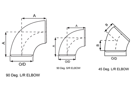
| Dimensions of Buttweld Elbows (ANSI B 16.9) (in mm) | ||||||||||||
| Center of End | ||||||||||||
| Nom. Pipe Size |
O.D. D |
900 L/R A |
45 S/R B |
90 S/R A |
||||||||
| Min | Nom | Max | Min | Nom | Max | Min | Nom | Max | Min | Nom | Max | |
| 1/2'' | 20 | 21 | 22 | 36 | 38 | 40 | 14 | 16 | 18 | - | - | - |
| 3/4'' | 26 | 27 | 28 | 27 | 29 | 31 | 9 | 11 | 13 | - | - | - |
| 1'' | 32 | 33 | 34 | 36 | 38 | 40 | 20 | 22 | 24 | 23 | 25 | 27 |
| 1 1/4'' | 41 | 42 | 43 | 46 | 48 | 50 | 23 | 25 | 27 | 30 | 32 | 34 |
| 1 1/2'' | 47 | 48 | 49 | 55 | 57 | 59 | 27 | 29 | 31 | 36 | 38 | 40 |
| 2'' | 59 | 60 | 61 | 74 | 76 | 78 | 33 | 35 | 37 | 49 | 51 | 53 |
| 2 1/2'' | 72 | 73 | 74 | 93 | 95 | 97 | 42 | 44 | 46 | 62 | 64 | 66 |
| 3'' | 88 | 89 | 90 | 112 | 114 | 116 | 49 | 51 | 53 | 74 | 76 | 78 |
| 4'' | 113 | 114 | 116 | 150 | 152 | 154 | 62 | 64 | 66 | 100 | 102 | 104 |
| 5'' | 140 | 141 | 144 | 188 | 190 | 192 | 77 | 79 | 81 | 125 | 127 | 129 |
| 6'' | 167 | 168 | 171 | 227 | 229 | 231 | 93 | 95 | 97 | 150 | 152 | 154 |
| 8'' | 217 | 219 | 221 | 303 | 305 | 307 | 125 | 127 | 129 | 201 | 203 | 205 |
| 10'' | 270 | 273 | 277 | 379 | 381 | 383 | 157 | 159 | 161 | 252 | 254 | 256 |
| 12'' | 321 | 324 | 328 | 454 | 457 | 460 | 187 | 190 | 193 | 302 | 305 | 308 |
| 14'' | 353 | 356 | 360 | 530 | 533 | 536 | 219 | 222 | 225 | 353 | 356 | 359 |
| 16'' | 403 | 406 | 410 | 607 | 610 | 613 | 251 | 254 | 257 | 403 | 406 | 409 |
| 18'' | 454 | 457 | 461 | 683 | 686 | 689 | 283 | 286 | 289 | 454 | 457 | 460 |
| 20'' | 503 | 508 | 514 | 759 | 762 | 765 | 315 | 318 | 321 | 505 | 508 | 511 |
| 24'' | 605 | 610 | 616 | 911 | 914 | 917 | 378 | 381 | 384 | 607 | 610 | 613 |
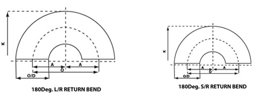
| Dimensions of Buttweld Bends (ANSI B 16.28) (in mm) | |||||||||||||||
| Center of Center | Back to Face | ||||||||||||||
| Nom. Pipe Size |
O.D. D |
1800 L/R A |
180 S/R A |
180 L/R K |
180 S/R K |
||||||||||
| Min | Nom | Max | Min | Nom | Max | Min | Nom | Max | Min | Nom | Max | Min | Nom | Max | |
| 1/2 | 20 | 21 | 22 | 69 | 76 | 83 | - | - | - | 41 | 48 | 55 | - | - | - |
| 3/4 | 26 | 27 | 28 | 50 | 57 | 64 | - | - | - | 36 | 43 | 50 | - | - | - |
| 1 | 32 | 33 | 34 | 69 | 76 | 83 | 44 | 51 | 58 | 49 | 56 | 63 | 34 | 41 | 48 |
| 1 1/4 | 41 | 42 | 43 | 88 | 95 | 102 | 57 | 64 | 71 | 63 | 70 | 77 | 45 | 52 | 59 |
| 1 1/2 | 47 | 48 | 49 | 107 | 114 | 121 | 69 | 76 | 83 | 76 | 83 | 90 | 55 | 62 | 69 |
| 2 | 59 | 60 | 61 | 145 | 152 | 159 | 95 | 102 | 109 | 99 | 106 | 113 | 74 | 81 | 88 |
| 2 1/2 | 72 | 73 | 74 | 184 | 191 | 198 | 120 | 127 | 134 | 125 | 132 | 139 | 93 | 100 | 107 |
| 3 | 88 | 89 | 90 | 222 | 229 | 236 | 145 | 152 | 159 | 152 | 159 | 166 | 114 | 121 | 128 |
| 4 | 113 | 114 | 116 | 298 | 305 | 312 | 196 | 203 | 210 | 203 | 210 | 217 | 152 | 159 | 166 |
| 5 | 140 | 141 | 144 | 374 | 381 | 388 | 247 | 254 | 261 | 255 | 262 | 269 | 190 | 197 | 204 |
| 6 | 167 | 168 | 171 | 450 | 457 | 464 | 298 | 305 | 312 | 306 | 313 | 320 | 230 | 237 | 244 |
| 8 | 217 | 219 | 221 | 603 | 610 | 617 | 399 | 406 | 413 | 407 | 414 | 421 | 306 | 313 | 320 |
| 10 | 270 | 273 | 277 | 752 | 762 | 772 | 498 | 508 | 518 | 511 | 518 | 525 | 384 | 391 | 398 |
| 12 | 321 | 324 | 328 | 904 | 914 | 924 | 600 | 610 | 620 | 612 | 619 | 626 | 460 | 467 | 474 |
| 14 | 353 | 356 | 360 | 1057 | 1067 | 1077 | 701 | 711 | 721 | 704 | 711 | 718 | 526 | 533 | 540 |
| 16 | 403 | 406 | 410 | 1209 | 1219 | 1229 | 803 | 813 | 823 | 806 | 813 | 820 | 603 | 610 | 617 |
| 18 | 454 | 457 | 461 | 1362 | 1372 | 1382 | 904 | 914 | 924 | 907 | 924 | 921 | 679 | 686 | 693 |
| 20 | 503 | 508 | 514 | 1514 | 1524 | 1534 | 1006 | 1016 | 1026 | 1009 | 1016 | 1023 | 755 | 762 | 769 |
| 24 | 605 | 610 | 616 | 1819 | 1829 | 1839 | 1209 | 1219 | 1229 | 1212 | 1219 | 1226 | 907 | 914 | 921 |
These pipe fittings work perfectly to stop fluid leakage and are known to be ideal compound connection that pipes can have.
Elbow:
The Butt Weld Elbow can be 45 Degrees, 90 Degrees and 180 Degrees
Bend:
The Bend can be 180 Degree L/R Return Bend and 180 Degree S/R Return Bend
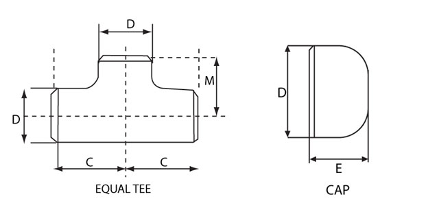
| Dimensions of Buttweld Fittings (ANSI B 16.9) (in mm) | ||||||||||||
| O.D. | Cap | Equal Tee | ||||||||||
| Nom. Pipe Size |
D |
E |
C |
M |
||||||||
| Min | Nom | Max | Min | Nom | Max | Min | Nom | Max | Min | Nom | Max | |
| 1/2'' | 20 | 21 | 22 | 21 | 25 | 29 | 23 | 25 | 27 | 23 | 25 | 27 |
| 3/4'' | 26 | 27 | 28 | 21 | 25 | 29 | 27 | 29 | 31 | 27 | 29 | 31 |
| 1'' | 32 | 33 | 34 | 34 | 38 | 42 | 36 | 38 | 40 | 36 | 38 | 40 |
| 1 1/4'' | 41 | 42 | 43 | 34 | 38 | 42 | 46 | 48 | 50 | 46 | 48 | 50 |
| 1 1/2'' | 47 | 48 | 49 | 34 | 38 | 42 | 55 | 57 | 59 | 55 | 57 | 59 |
| 2'' | 59 | 60 | 61 | 34 | 38 | 42 | 62 | 64 | 66 | 62 | 64 | 66 |
| 2 1/2'' | 72 | 73 | 74 | 34 | 38 | 42 | 74 | 76 | 78 | 74 | 76 | 78 |
| 3'' | 88 | 89 | 90 | 47 | 51 | 55 | 84 | 86 | 88 | 84 | 86 | 88 |
| 4'' | 113 | 114 | 116 | 60 | 64 | 68 | 103 | 105 | 107 | 103 | 105 | 107 |
| 5'' | 140 | 141 | 144 | 69 | 76 | 83 | 122 | 124 | 126 | 122 | 124 | 126 |
| 6'' | 167 | 168 | 171 | 82 | 89 | 96 | 141 | 143 | 145 | 141 | 143 | 145 |
| 8'' | 217 | 219 | 221 | 95 | 102 | 109 | 176 | 178 | 180 | 176 | 178 | 180 |
| 10'' | 270 | 273 | 277 | 120 | 127 | 134 | 214 | 216 | 218 | 214 | 216 | 218 |
| 12'' | 321 | 324 | 328 | 145 | 152 | 159 | 251 | 254 | 257 | 251 | 254 | 257 |
| 14'' | 353 | 356 | 360 | 158 | 165 | 172 | 276 | 279 | 282 | 276 | 279 | 282 |
| 16'' | 403 | 406 | 410 | 171 | 178 | 185 | 302 | 305 | 308 | 302 | 305 | 308 |
| 18'' | 454 | 457 | 461 | 196 | 203 | 210 | 340 | 343 | 346 | 340 | 343 | 346 |
| 20'' | 503 | 508 | 514 | 222 | 229 | 236 | 378 | 381 | 384 | 378 | 381 | 384 |
| 24'' | 605 | 610 | 616 | 260 | 267 | 274 | 429 | 432 | 435 | 429 | 432 | 435 |
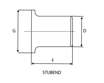
| Dimensions of Buttweld Stubends (ANSI B 16.9 & MSS SP 43) (in mm) | |||||||||||
| O.D. | Stubend | B 16.9 | MSS SP 43 | ||||||||
| Nom. Pipe Size |
D |
G |
F |
F |
|||||||
| Min | Nom | Max | Min | Max | Min | Nom | Max | Min | Nom | Max | |
| 1/2 | 20 | 21 | 22 | 34 | 35 | 74 | 76 | 78 | 49 | 51 | 53 |
| 3/4 | 26 | 27 | 28 | 42 | 43 | 74 | 76 | 78 | 49 | 51 | 53 |
| 1 | 32 | 33 | 34 | 50 | 51 | 100 | 102 | 104 | 49 | 51 | 53 |
| 1 1/4 | 41 | 42 | 43 | 63 | 64 | 100 | 102 | 104 | 49 | 51 | 53 |
| 1 1/2 | 47 | 48 | 49 | 72 | 73 | 100 | 102 | 104 | 49 | 51 | 53 |
| 2 | 59 | 60 | 61 | 91 | 92 | 150 | 152 | 154 | 62 | 64 | 66 |
| 2 1/2 | 72 | 73 | 74 | 104 | 105 | 150 | 152 | 154 | 62 | 64 | 66 |
| 3 | 88 | 89 | 90 | 126 | 127 | 150 | 152 | 154 | 62 | 64 | 66 |
| 4 | 113 | 114 | 116 | 156 | 157 | 150 | 152 | 154 | 74 | 76 | 78 |
| 5 | 140 | 141 | 144 | 185 | 186 | 201 | 203 | 205 | 74 | 76 | 78 |
| 6 | 167 | 168 | 171 | 215 | 216 | 201 | 203 | 205 | 87 | 89 | 91 |
| 8 | 217 | 219 | 221 | 269 | 270 | 201 | 203 | 205 | 100 | 102 | 104 |
| 10 | 270 | 273 | 277 | 322 | 324 | 252 | 254 | 256 | 125 | 127 | 129 |
| 12 | 321 | 324 | 328 | 379 | 381 | 252 | 254 | 256 | 150 | 152 | 154 |
| 14 | 353 | 356 | 360 | 411 | 413 | 302 | 305 | 308 | 150 | 152 | 154 |
| 16 | 403 | 406 | 410 | 468 | 470 | 302 | 305 | 308 | 150 | 152 | 154 |
| 18 | 454 | 457 | 461 | 531 | 533 | 302 | 305 | 308 | 150 | 152 | 154 |
| 20 | 503 | 508 | 514 | 582 | 584 | 302 | 305 | 308 | 150 | 152 | 154 |
| 24 | 605 | 610 | 616 | 690 | 692 | 302 | 305 | 308 | 150 | 152 | 154 |
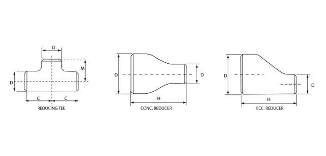
| Dimensions of Buttweld Reducing Tees and Reducers (ANSI B 16.9) (in mm) | |||||||||||||||
| Nom. Pipe Size |
Outside Diameter of Reducing Tees and Reducer | Center to End Length of Reducing Tees and Reducer | End-to-End lenght of Reducers | ||||||||||||
| NPS | Run D |
Branch D |
Run C |
Branch M |
H | ||||||||||
| Min | Nom | Max | Min | Nom | Max | Min | Nom | Max | Min | Nom | Max | Min | Nom | Max | |
| 3/4'' x 1/2'' | 26 | 27 | 28 | 20 | 21 | 22 | 27 | 28 | 29 | 27 | 29 | 31 | 36 | 38 | 40 |
| 3/4'' x 3/8'' | 26 | 27 | 28 | 16 | 17 | 18 | 27 | 29 | 31 | 27 | 29 | 31 | 36 | 38 | 40 |
| 1'' x 3/4'' | 32 | 33 | 34 | 26 | 27 | 28 | 36 | 38 | 40 | 36 | 38 | 40 | 49 | 51 | 53 |
| 1'' x 1/2'' | 32 | 33 | 34 | 20 | 21 | 22 | 36 | 38 | 40 | 36 | 38 | 40 | 49 | 51 | 53 |
| 1-1/4'' x 1'' | 41 | 42 | 43 | 32 | 33 | 34 | 46 | 48 | 50 | 46 | 48 | 50 | 49 | 51 | 53 |
| 1-1/4'' x 3/4'' | 41 | 42 | 43 | 26 | 27 | 28 | 46 | 48 | 50 | 46 | 48 | 50 | 49 | 51 | 53 |
| 1-1/4'' x 1/2'' | 41 | 42 | 43 | 20 | 21 | 22 | 46 | 48 | 50 | 46 | 48 | 50 | 49 | 51 | 53 |
| 1-1/2'' x 1/4'' | 47 | 48 | 49 | 41 | 42 | 43 | 55 | 57 | 59 | 55 | 57 | 59 | 62 | 64 | 66 |
| 1-1/2'' x 1'' | 47 | 48 | 49 | 32 | 33 | 34 | 55 | 57 | 59 | 55 | 57 | 59 | 62 | 64 | 66 |
| 1-1/2'' x 3/4'' | 47 | 48 | 49 | 26 | 27 | 28 | 55 | 57 | 59 | 55 | 57 | 59 | 62 | 64 | 66 |
| 1-1/2'' x 1/2'' | 47 | 48 | 49 | 20 | 21 | 22 | 55 | 57 | 59 | 55 | 57 | 59 | 62 | 64 | 66 |
| 2'' x 1-1/2'' | 59 | 60 | 61 | 47 | 48 | 49 | 62 | 64 | 66 | 58 | 60 | 62 | 74 | 76 | 78 |
| 2'' x 1-1/4'' | 59 | 60 | 61 | 41 | 42 | 43 | 62 | 64 | 66 | 55 | 57 | 59 | 74 | 76 | 78 |
| 2'' x 1'' | 59 | 60 | 61 | 32 | 33 | 34 | 62 | 64 | 66 | 49 | 51 | 53 | 74 | 76 | 78 |
| 2'' x 3/4'' | 59 | 60 | 61 | 26 | 27 | 28 | 62 | 64 | 66 | 42 | 44 | 46 | 74 | 76 | 78 |
| 2-1/2'' x 2'' | 72 | 73 | 74 | 59 | 60 | 61 | 74 | 76 | 78 | 68 | 70 | 72 | 87 | 89 | 91 |
| 2-1/2'' x1-1/ 2'' | 72 | 73 | 74 | 47 | 48 | 49 | 74 | 76 | 78 | 65 | 67 | 69 | 87 | 89 | 91 |
| 2-1/2'' x1-1/4'' | 72 | 73 | 74 | 41 | 42 | 43 | 74 | 76 | 78 | 62 | 64 | 66 | 87 | 89 | 91 |
| 2-1/2'' x 1'' | 72 | 73 | 74 | 32 | 33 | 34 | 74 | 76 | 78 | 55 | 57 | 59 | 87 | 89 | 91 |
| 3'' x 2-1/2'' | 88 | 89 | 90 | 72 | 73 | 74 | 84 | 86 | 88 | 81 | 83 | 85 | 87 | 89 | 91 |
| 3'' x 2'' | 88 | 89 | 90 | 59 | 60 | 61 | 84 | 86 | 88 | 74 | 76 | 78 | 87 | 89 | 91 |
| 3'' x 1-1/2'' | 88 | 89 | 90 | 47 | 48 | 49 | 84 | 86 | 88 | 71 | 73 | 75 | 87 | 89 | 91 |
| 3'' x 1-1/4'' | 88 | 89 | 90 | 41 | 42 | 43 | 84 | 86 | 88 | 68 | 70 | 72 | 87 | 89 | 91 |
| 4'' x 3'' | 113 | 114 | 116 | 88 | 89 | 90 | 103 | 105 | 107 | 96 | 98 | 100 | 100 | 102 | 104 |
| 4'' x 2 -1/2'' | 113 | 114 | 116 | 72 | 73 | 74 | 103 | 105 | 107 | 93 | 95 | 97 | 100 | 102 | 104 |
| 4'' x 2'' | 113 | 114 | 116 | 59 | 60 | 61 | 103 | 105 | 107 | 87 | 89 | 91 | 100 | 102 | 104 |
| 4'' x 1 -1/2'' | 113 | 114 | 116 | 47 | 48 | 49 | 103 | 105 | 107 | 84 | 86 | 88 | 100 | 102 | 104 |
| 5'' x 4'' | 140 | 141 | 144 | 113 | 114 | 116 | 122 | 124 | 126 | 115 | 117 | 119 | 125 | 127 | 129 |
| 5'' x 3'' | 140 | 141 | 144 | 88 | 89 | 90 | 122 | 124 | 126 | 109 | 111 | 113 | 125 | 127 | 129 |
| 5'' x 2-1/2'' | 140 | 141 | 144 | 72 | 73 | 74 | 122 | 124 | 126 | 106 | 108 | 110 | 125 | 127 | 129 |
| 5'' x 2'' | 140 | 141 | 144 | 59 | 60 | 61 | 122 | 124 | 126 | 103 | 105 | 107 | 125 | 127 | 129 |
| 6'' x 5'' | 167 | 168 | 171 | 140 | 141 | 144 | 141 | 143 | 145 | 135 | 137 | 139 | 138 | 140 | 142 |
| 6'' x 4'' | 167 | 168 | 171 | 113 | 114 | 116 | 141 | 143 | 145 | 128 | 130 | 132 | 138 | 140 | 142 |
| 6'' x 3'' | 167 | 168 | 171 | 88 | 89 | 90 | 141 | 143 | 145 | 122 | 124 | 126 | 138 | 140 | 142 |
| 6'' x 2-1/2'' | 167 | 168 | 171 | 72 | 73 | 74 | 141 | 143 | 145 | 119 | 121 | 123 | 138 | 140 | 142 |
| 8'' x 6'' | 217 | 219 | 221 | 167 | 168 | 171 | 176 | 178 | 180 | 166 | 168 | 170 | 150 | 152 | 154 |
| 8'' x 5'' | 217 | 219 | 221 | 140 | 141 | 144 | 176 | 178 | 180 | 160 | 162 | 164 | 150 | 152 | 154 |
| 8'' x 4'' | 217 | 219 | 221 | 113 | 114 | 116 | 176 | 178 | 180 | 154 | 156 | 158 | 150 | 152 | 154 |
| 10'' x 8'' | 270 | 273 | 277 | 217 | 219 | 221 | 214 | 216 | 218 | 201 | 203 | 205 | 176 | 178 | 180 |
| 10'' x 6'' | 270 | 273 | 277 | 167 | 168 | 171 | 214 | 216 | 218 | 192 | 194 | 196 | 176 | 178 | 180 |
| 10'' x 5'' | 270 | 273 | 277 | 140 | 141 | 144 | 214 | 216 | 218 | 189 | 191 | 193 | 176 | 178 | 180 |
| 10'' x 4'' | 270 | 273 | 277 | 113 | 114 | 116 | 214 | 216 | 218 | 182 | 184 | 186 | 176 | 178 | 180 |
| 12'' x 10'' | 321 | 324 | 328 | 270 | 273 | 277 | 251 | 254 | 257 | 238 | 241 | 244 | 200 | 203 | 206 |
| 12'' x 8'' | 321 | 324 | 328 | 217 | 219 | 221 | 251 | 254 | 257 | 226 | 229 | 232 | 200 | 203 | 206 |
| 12'' x 6'' | 321 | 324 | 328 | 167 | 168 | 171 | 251 | 254 | 257 | 216 | 219 | 222 | 200 | 203 | 206 |
| 12'' x 5'' | 321 | 324 | 328 | 140 | 141 | 144 | 251 | 254 | 257 | 213 | 216 | 219 | 200 | 203 | 206 |
| 14'' x 12'' | 353 | 356 | 360 | 321 | 324 | 328 | 276 | 279 | 282 | 267 | 270 | 273 | 327 | 330 | 333 |
| 14'' x 10'' | 353 | 356 | 360 | 270 | 273 | 277 | 276 | 279 | 282 | 254 | 257 | 260 | 327 | 330 | 333 |
| 14'' x 8'' | 353 | 356 | 360 | 217 | 219 | 221 | 276 | 279 | 282 | 245 | 248 | 251 | 327 | 330 | 333 |
| 14'' x 6'' | 353 | 356 | 360 | 167 | 168 | 171 | 276 | 279 | 282 | 235 | 238 | 241 | 327 | 330 | 333 |
| 16'' x 14'' | 403 | 406 | 410 | 353 | 356 | 360 | 302 | 305 | 308 | 302 | 305 | 308 | 353 | 356 | 359 |
| 16'' x 12'' | 403 | 406 | 410 | 321 | 324 | 328 | 302 | 305 | 308 | 292 | 295 | 298 | 353 | 356 | 359 |
| 16'' x 10'' | 403 | 406 | 410 | 270 | 273 | 277 | 302 | 305 | 308 | 280 | 283 | 286 | 353 | 356 | 359 |
| 16'' x 8'' | 403 | 406 | 410 | 217 | 219 | 221 | 302 | 305 | 308 | 270 | 273 | 276 | 353 | 356 | 359 |
| 18'' x 16'' | 454 | 457 | 461 | 403 | 406 | 410 | 340 | 343 | 346 | 327 | 330 | 333 | 378 | 381 | 384 |
| 18'' x 14'' | 454 | 457 | 461 | 353 | 356 | 360 | 340 | 343 | 346 | 327 | 330 | 333 | 378 | 381 | 384 |
| 18'' x 12'' | 454 | 457 | 461 | 321 | 324 | 328 | 340 | 343 | 346 | 318 | 321 | 324 | 378 | 381 | 384 |
| 18'' x 10'' | 454 | 457 | 461 | 270 | 273 | 277 | 340 | 343 | 346 | 305 | 308 | 311 | 378 | 381 | 384 |
| 20'' x 18'' | 503 | 508 | 514 | 454 | 457 | 461 | 378 | 381 | 384 | 365 | 367 | 371 | 505 | 508 | 511 |
| 20'' x 16'' | 503 | 508 | 514 | 403 | 406 | 410 | 378 | 381 | 384 | 353 | 356 | 359 | 505 | 508 | 511 |
| 20'' x 14'' | 503 | 508 | 514 | 353 | 356 | 360 | 378 | 381 | 384 | 353 | 356 | 359 | 505 | 508 | 511 |
| 20'' x 12'' | 503 | 508 | 514 | 321 | 324 | 328 | 378 | 381 | 384 | 343 | 346 | 349 | 505 | 508 | 511 |
| 20'' x 10'' | 503 | 508 | 514 | 270 | 273 | 277 | 378 | 381 | 384 | 330 | 333 | 336 | 505 | 508 | 511 |
| 24'' x 20'' | 605 | 610 | 616 | 503 | 508 | 514 | 429 | 432 | 435 | 429 | 432 | 435 | 505 | 508 | 511 |
| 24'' x 18'' | 605 | 610 | 616 | 454 | 457 | 461 | 429 | 432 | 435 | 416 | 419 | 422 | 505 | 508 | 511 |
| 24'' x 16'' | 605 | 610 | 616 | 403 | 406 | 410 | 429 | 432 | 435 | 403 | 406 | 410 | 505 | 508 | 511 |
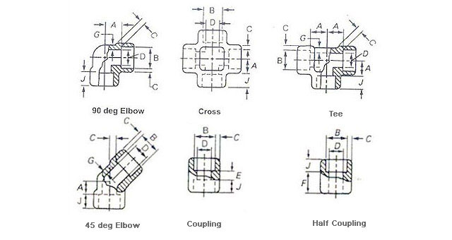
| DIMENSIONS OF SOCKET-WELD FITTINGS (ANSI B 16.11) (in mm) | ||||||||||||||||||||||
| Nominal Pipe Size |
Socket Bore Dita(2) B |
Bore Diameter of (2) Fittings (D) |
Socket Wall Thickness-C(1) | Depth of Socket J Min |
Center of Bottom of Socket-A | Laying Lenghts |
Tolerances | |||||||||||||||
| Pressure Class Designation |
Pressure Class Designation | 900 Elbows Tess and Crosses |
450 Elbows | E | Half F |
A | E | F | ||||||||||||||
| 3000 | 6000 | 9000 | Pressure Class Designation | |||||||||||||||||||
| 3000 | 6000 | 9000 | Ave. | Min. | Ave. | Min. | Ave. | Min. | 3000 | 6000 | 9000 | 3000 | 6000 | 9000 | ||||||||
| 1/8'' | 10.92 | 7.59 | 4.80 | 3.17 | 3.17 | 3.96 | 3.42 | 9.65 | 11.17 | 11.17 | 7.87 | 7.87 | 6.35 | 15.74 | 0.76 | 1.52 | 0.76 | |||||
| 10.33 | 6.07 | 3.20 | ||||||||||||||||||||
| 1/4'' | 14.35 | 10.00 | 7.11 | 3.78 | 3.30 | 4.59 | 4.01 | 9.65 | 11.17 | 13.46 | 7.87 | 7.87 | 6.35 | 15.74 | 0.76 | 1.52 | 0.76 | |||||
| 14.09 | 8.48 | 5.58 | ||||||||||||||||||||
| 3/8'' | 17.78 | 13.28 | 9.88 | 4.01 | 3.50 | 5.02 | 4.36 | 9.65 | 13.46 | 15.74 | 7.87 | 11.17 | 6.35 | 17.52 | 1.52 | 3.04 | 1.52 | |||||
| 17.52 | 11.76 | 8.35 | ||||||||||||||||||||
| 1/2'' | 22.04 | 16.56 | 12.54 | 7.62 | 4.68 | 4.08 | 5.96 | 5.18 | 9.34 | 8.17 | 9.65 | 15.74 | 19.05 | 25.40 | 11.17 | 12.70 | 15.74 | 9.65 | 22.35 | 1.52 | 3.04 | 1.52 |
| 21.71 | 15.03 | 11.02 | 6.09 | |||||||||||||||||||
| 3/4'' | 27.30 | 21.69 | 16.30 | 11.78 | 4.90 | 4.26 | 6.95 | 6.04 | 9.77 | 8.55 | 12.70 | 19.05 | 22.35 | 28.44 | 12.70 | 14.22 | 19.05 | 9.65 | 23.87 | 1.52 | 3.04 | 1.52 |
| 27.05 | 20.16 | 14.78 | 10.26 | |||||||||||||||||||
| 1'' | 34.03 | 27.40 | 21.46 | 15.97 | 5.68 | 4.97 | 7.92 | 6.93 | 11.37 | 9.95 | 12.70 | 22.35 | 26.92 | 31.75 | 14.22 | 17.52 | 20.57 | 12.70 | 28.44 | 2.03 | 4.06 | 2.03 |
| 33.78 | 25.88 | 19.93 | 14.45 | |||||||||||||||||||
| 1.1/4'' | 42.79 | 35.81 | 30.22 | 23.52 | 6.07 | 5.28 | 7.92 | 6.93 | 12.14 | 10.61 | 12.70 | 26.92 | 31.75 | 35.05 | 17.52 | 20.51 | 22.35 | 12.70 | 30.22 | 2.03 | 4.06 | 2.03 |
| 42.54 | 34.30 | 28.70 | 21.99 | |||||||||||||||||||
| 1.1/2'' | 48.89 | 41.65 | 34.74 | 28.70 | 6.35 | 5.53 | 8.91 | 7.79 | 12.70 | 11.12 | 12.70 | 31.70 | 38.10 | 38.10 | 20.57 | 25.40 | 25.40 | 12.70 | 31.75 | 2.03 | 4.06 | 2.03 |
| 48.64 | 40.13 | 33.22 | 27.17 | |||||||||||||||||||
| 2'' | 61.36 | 53.26 | 43.61 | 38.93 | 6.93 | 6.04 | 10.92 | 9.49 | 13.84 | 12.11 | 15.74 | 38.10 | 41.14 | 53.84 | 25.40 | 28.44 | 28.44 | 19.05 | 41.14 | 2.03 | 4.06 | 2.03 |
| 61.11 | 52.20 | 41.90 | 37.41 | |||||||||||||||||||
| 2.1/2'' | 74.18 | 64.23 | 8.76 | 7.67 | 15.74 | 41.14 | 28.44 | 19.05 | 43.09 | 2.54 | 5.08 | 2.54 | ||||||||||
| 73.81 | 61.18 | |||||||||||||||||||||
| 3'' | 90.17 | 79.45 | 9.52 | 8.30 | 15.74 | 57.15 | 31.75 | 19.05 | 44.45 | 2.54 | 5.08 | 2.54 | ||||||||||
| 89.78 | 76.40 | |||||||||||||||||||||
| 4'' | 115.82 | 103.78 | 10.69 | 9.34 | 19.05 | 66.54 | 41.14 | 19.05 | 47.75 | 2.54 | 5.08 | 2.54 | ||||||||||
| 115.44 | 100.73 | |||||||||||||||||||||
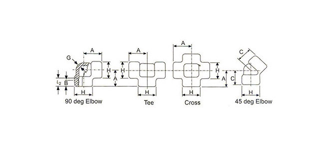
| DIMENSIONS OF THREADED FITTINGS (ANSI B 16.11) (in mm) | ||||||||||||||
| Nominal Pipe Size |
||||||||||||||
| A | C | H | G | Min(1) | ||||||||||
| 2000 | 3000 | 6000 | 2000 | 3000 | 6000 | 2000 | 3000 | 6000 | 2000 | 3000 | 6000 | B | L2 | |
| 1/8'' | 20.57 | 20.57 | 24.63 | 17.52 | 17.52 | 18.93 | 22.35 | 22.30 | 25.40 | 3.175 | 3.110 | 6.350 | 6.303 | 6.700 |
| 1/4'' | 20.57 | 24.63 | 28.44 | 17.52 | 18.93 | 22.35 | 22.35 | 25.40 | 33.20 | 3.175 | 3.302 | 6.604 | 8.128 | 10.205 |
| 3/8'' | 24.63 | 28.44 | 33.27 | 18.93 | 22.35 | 25.40 | 25.40 | 33.27 | 38.10 | 3.175 | 2.505 | 6.985 | 9.544 | 10.298 |
| 1/2'' | 28.44 | 33.27 | 38.10 | 44.45 | 25.40 | 28.44 | 33.27 | 38.10 | 45.97 | 3.175 | 4.089 | 8.153 | 10.922 | 13.555 |
| 3/4'' | 33.27 | 38.10 | 44.45 | 25.40 | 28.44 | 33.27 | 38.10 | 45.97 | 55.62 | 3.175 | 4.318 | 8.534 | 12.700 | 13.860 |
| 1'' | 38.10 | 44.45 | 50.80 | 28.44 | 33.27 | 35.05 | 45.97 | 55.62 | 61.97 | 3.688 | 4.978 | 9.931 | 14.732 | 17.343 |
| 1-1/4'' | 44.45 | 50.80 | 60.45 | 33.27 | 35.04 | 42.92 | 55.62 | 61.97 | 75.43 | 3.886 | 5.283 | 10.591 | 17.018 | 17.952 |
| 1-1/2'' | 50.80 | 60.45 | 76.02 | 33.05 | 42.92 | 43.68 | 61.97 | 75.43 | 84.07 | 4.013 | 5.562 | 11.074 | 17.780 | 18.376 |
| 2'' | 60.45 | 63.50 | 82.55 | 42.92 | 43.68 | 52.32 | 75.43 | 84.07 | 101.60 | 4.267 | 7.137 | 12.090 | 19.050 | 19.138 |
| 2-1/2'' | 76.20 | 82.55 | 95.25 | 52.37 | 52.32 | 63.50 | 91.94 | 101.60 | 120.65 | 5.613 | 7.645 | 15.290 | 23.622 | 28.905 |
| 3'' | 85.85 | 95.25 | 106.42 | 63..50 | 63.50 | 79.24 | 109.47 | 120.65 | 146.05 | 5.994 | 8.839 | 18.637 | 25.408 | 30.500 |
| 4'' | 106.42 | 114.30 | 114.30 | 78.24 | 78.24 | 79.24 | 146.05 | 152.40 | 152.40 | 6.555 | 11.669 | 18.684 | 27.777 | 33.000 |
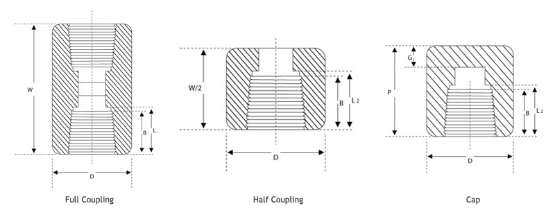
| DIMENSIOS OF COUPLINGS & CAPS (BS 3799) (in mm) | |||||||||
| Nominal Pipe Size |
End to End Couplings W |
End to End Caps P |
Outside Diameter D |
End Wall Thickness G Min |
Length of thread Min. (1) |
||||
| 3000 & 6000 | 3000 | 6000 | 3000 | 6000 | 3000 | 6000 | B | L2 | |
| 1/8'' | 31.8 | 19.1 | 15.7 | 22.4 | 4.8 | - | 6.4 | 6.7 | |
| 1/4'' | 35.1 | 25.4 | 26.9 | 19.1 | 25.4 | 4.8 | 6.4 | 8.1 | 10.2 |
| 3/8'' | 38.1 | 25.4 | 26.9 | 22.4 | 31.8 | 4.8 | 6.4 | 9.1 | 10.4 |
| 1/2'' | 47.8 | 31.8 | 33.3 | 28.4 | 38.1 | 6.4 | 7.9 | 10.9 | 13.6 |
| 3/4'' | 50.8 | 36.6 | 38.1 | 35.1 | 44.5 | 6.4 | 7.9 | 12.7 | 13.9 |
| 1'' | 60.5 | 41.1 | 42.9 | 44.5 | 57.2 | 9.7 | 11.2 | 14.7 | 17.3 |
| 1-1/4'' | 66.5 | 44.5 | 46.0 | 57.2 | 63.5 | 9.7 | 11.2 | 17.0 | 18.0 |
| 1-1/2'' | 79.2 | 44.5 | 47.8 | 63.5 | 76.2 | 11.2 | 12.7 | 17.8 | 18.4 |
| 2'' | 85.9 | 47.8 | 50.8 | 76.2 | 91.9 | 12.7 | 15.7 | 19.1 | 19.2 |
| 2-1/2'' | 91.9 | 60.5 | 63.5 | 91.9 | 108.0 | 15.7 | 19.1 | 23.6 | 28.9 |
| 3'' | 108.0 | 68.3 | 74.7 | 139.7 | 158.8 | 22.4 | 28.4 | 27.7 | 33.0 |
1.) Dimension B is minimum length of perfect thread. The length of useful thread (B plus threads with fully formed roots and flat creats) shall not be less Than L2 (effective length of external thread) required by American National Standard for Pipe Threads (ANSI B2. 1)
Class 2000 and NPS 1/8 class 6000 coupling, half couplings and caps are not included in this standard.
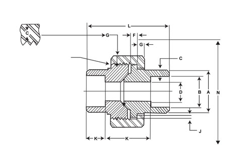
| DIMENSIONS OF SOCKET - WELD AND THREADED UNION (BS3799) (in mm) |
||||||||||||
| Nom. Pipe Size | Pipe End Min | Socket Bore Dia. | Socket Wall Min. | Water Way Bore | Laying Length | Male Flange Min. | Nut Min. | Threads Per 25.4 Max | Bearing Min. | Depth of Socket Min. | Length Assem. Nominal | Clear Assem. Nut |
| A | B | C | D | E | F | G | H | J | K | L | N | |
| 1/8 | 21.8 | 10.92 10.67 |
3.17 | 6.83 6.43 |
22.4 19.0 |
3.17 | 3.17 | 16 | 1.24 | 9.6 | 41.1 | 49.0 |
| ¼ | 21.8 | 14.22 13.97 |
3.30 | 9.85 9.45 |
22.4 19.0 |
3.17 | 3.17 | 19 | 1.24 | 9.6 | 41.4 | 49.0 |
| 3/8 | 25.9 | 17.78 17.53 |
3.48 | 13.92 13.51 |
26.9 20.6 |
3.43 | 3.43 | 14 | 1.37 | 9.6 | 46.0 | 55.0 |
| ½ | 31.2 | 21.84 21.59 |
4.06 | 17.47 17.07 |
26.9 20.6 |
3.68 | 3.68 | 14 | 1.50 | 9.6 | 49.0 | 57.0 |
| ¾ | 37.1 | 27.18 26.92 |
4.27 | 21.79 21.39 |
31.8 25.4 |
4.06 | 4.06 | 11 | 1.68 | 12.7 | 56.9 | 67.0 |
| 1 | 45.5 | 34.04 33.78 |
4.95 | 28.14 27.74 |
34.3 26.2 |
4.57 | 4.44 | 11 | 1.85 | 12.7 | 62.0 | 79.0 |
| 11/4 | 54.9 | 42.67 42.42 |
5.28 | 35.76 35.36 |
40.6 32.5 |
5.33 | 5.21 | 11 | 2.13 | 12.7 | 71.1 | 94.0 |
| 11/2 | 61.5 | 48.77 48.51 |
5.54 | 41.61 41.20 |
42.2 34.0 |
5.84 | 5.59 | 10 | 2.31 | 12.7 | 75.5 | 111.0 |
| 2 | 75.2 | 61.47 61.21 |
6.05 | 52.53 52.12 |
45.3 37.3 |
6.60 | 6.35 | 10 | 2.69 | 15.8 | 86.1 | 132.0 |
| 21/2 | 91.7 | 74.17 73.66 |
7.65 | 64.72 64.31 |
61.7 52.1 |
7.49 | 7.11 | 8 | 3.07 | 15.8 | 102.4 | 148.0 |
| 3 | 109.2 | 90.17 89.66 |
8.31 | 77.67 77.27 |
63.8 53.6 |
8.25 | 8.00 | 8 | 3.53 | 15.8 | 109.0 | 175.0 |
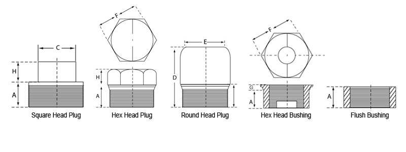
| DIMENSIONS OF STEEL PLUG & BUSHINGS (BS 3799) (In mm) | ||||||||
| Nominal Pipe Size |
Length (Minimim) A |
|||||||
| Plugs Square Head | Plugs Round Head | Hex Plugs & Bushings | ||||||
| Height of Square (Minimum) B |
Width Flats (Minimum) C |
Nominal Diameter of Head E |
Length (Minimum) D |
Width Flats (Nominal) F |
Hex Height (Min.) | |||
| Bushing G |
Plug H |
|||||||
| 1/8'' | 9.7 | 6.6 | 7.1 | 10.4 | 35.1 | 11.2 | - | 6.4 |
| 1/4'' | 11.2 | 6.6 | 9.7 | 13.5 | 41.1 | 15.7 | 3.0 | 6.4 |
| 3/8'' | 12.7 | 7.9 | 11.2 | 17.5 | 41.1 | 17.5 | 4.1 | 7.9 |
| 1/2'' | 14.2 | 9.7 | 14.2 | 21.3 | 44.5 | 22.4 | 4.8 | 7.9 |
| 3/4'' | 15.7 | 11.2 | 15.7 | 26.9 | 44.5 | 26.9 | 5.6 | 9.7 |
| 1'' | 19.1 | 12.7 | 20.6 | 33.3 | 50.8 | 35.1 | 6.4 | 9.7 |
| 1-1/4'' | 20.6 | 14.2 | 23.9 | 42.9 | 50.8 | 44.5 | 7.1 | 14.2 |
| 1-1/2'' | 20.6 | 15.7 | 28.4 | 48.5 | 50.8 | 50.8 | 7.9 | 15.7 |
| 2'' | 22.4 | 17.5 | 33.3 | 60.5 | 63.5 | 63.5 | 8.6 | 17.5 |
| 2-2/2'' | 26.9 | 19.1 | 38.1 | 73.2 | 69.9 | 76.2 | 9.7 | 19.1 |
| 3'' | 28.4 | 20.6 | 42.9 | 88.9 | 69.9 | 88.9 | 10.4 | 20.6 |
| 4'' | 31.8 | 25.4 | 53.5 | 114.3 | 76.2 | 117.3 | 12.7 | 25.4 |
CAUTIONARY NOTE REGARDING HEX HEAD BUSHINGS : Hex head Bushings of one size reduction should not be used in services wherein they might be subject to harmful and forces other than internal pressures.
Nippled olets are available in different sizes which makes them useful for various industrial applications. These can withstand extremely high pressure & can also be used like detachable or permanent thread connections. The other qualities they have are that they are abrasion resistant & durable.
| Run-Pipe Size | outlet Size | Wall – T | Total Length - L | G | Unit Weight (kg) |
| (in mm) | |||||
| 36-3/4 | ½ | 7.3 | 88.9 | 23.9 | 0.36 |
| 36-1 | ¾ | 7.9 | 88.9 | 30.2 | 0.56 |
| 36-1 ¼ | 1 | 8.9 | 88.9 | 36.6 | 0.84 |
| 36-1 ½ | 1 ¼ | 9.7 | 88.9 | 44.5 | 1.22 |
| 36-2 | 1 ½ | 10.2 | 88.9 | 50.8 | 2.00 |
| 36-2 ½ | 2 | 11.2 | 88.9 | 65.0 | 3.12 |
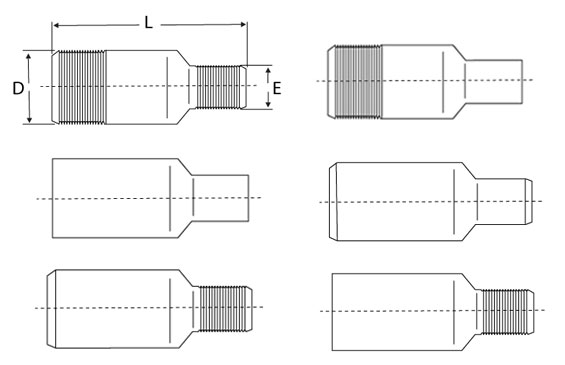
Swaged nippled olets are available in different technical specifications and have extremely high resistance to carburization & oxidation. These nippolets have good weldability also. Made from supreme quality of stainless steel & have their usage in engineering projects and in fabrication industry.
| Large end Size - D | Small and Size - E | Length -L |
| (in mm) | ||
| ½ | 3/8 – 1/8 | 70 |
| ¾ | 12/ -1/8 | 76 |
| 1 | ¾-1/8 | 89 |
| 1 ¼ | 1-1/8 | 102 |
| 1 ½ | 1 ¼ -1/8 | 114 |
| 2 | 1 ½ -1/8 | 165 |
| 2 ½ | 2-1/8 | 178 |
| 3 | 2 ½ – 1/8 | 203 |
| 3 ½ | 3-18 | 203 |
| 4 | 3 ½ – 1/8 | 229 |
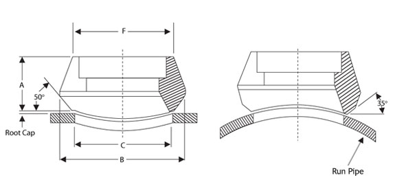
Socket olets are highly resistant to corrosion and heat. Even when exposed to high pressure and temperature applications they continue to maintain their strength.
| outlet Size | A | B | C | F | ||||
| (in mm) | ||||||||
| Nominal Bore | 3000 # | 6000 # | 3000 # | 6000# | 3000# | 6000# | 3000# | 6000# |
| ½ | 25.4 | 31.8 | 34.9 | 44.5 | 23.8 | 19.1 | 25.4 | 39.69 |
| ¾ | 27.0 | 36.5 | 44.5 | 50.8 | 30.2 | 25.4 | 31.71 | 45.24 |
| 1 | 33.3 | 39.7 | 54.0 | 61.9 | 36.5 | 33.3 | 36.51 | 57.15 |
| 1 1/4 | 33.3 | 41.3 | 65.1 | 69.9 | 44.5 | 38.1 | 46.04 | 65.09 |
| 1 1/2 | 34.9 | 42.9 | 73.0 | 82.6 | 50.8 | 49.2 | 55.56 | 76.20 |
| 2 | 38.1 | 52.4 | 88.9 | 103.2 | 65.1 | 69.9 | 61.91 | 92.08 |
| 2 1/2 | 46.0 | - | 103.2 | - | 76.2 | - | 74.61 | - |
| 3 | 50.8 | - | 122.2 | - | 93.7 | - | 87.31 | - |
| 4 | 57.2 | - | 152.4 | - | 120.7 | - | 105.0 | - |
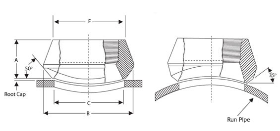
| outlet Size | A | B | C | F | ||||
| (in mm) | ||||||||
| Nominal Bore | 3000 # | 6000 # | 3000 # | 6000# | 3000# | 6000# | 3000# | 6000# |
| ½ | 25.4 | 31.8 | 34.9 | 44.5 | 23.8 | 19.1 | 50.8 | 63.5 |
| ¾ | 27.0 | 36.5 | 44.5 | 50.8 | 30.2 | 25.4 | 63.5 | 79.3 |
| 1 | 33.3 | 39.7 | 54.0 | 61.9 | 36.5 | 33.3 | 73.0 | 92.0 |
| 1 1/4 | 33.3 | 41.3 | 65.1 | 69.9 | 44.5 | 38.1 | 92.0 | 114.3 |
| 1 1/2 | 34.9 | 42.9 | 73.0 | 82.6 | 50.8 | 49.2 | 111.1 | 130.1 |
| 2 | 38.1 | 52.4 | 88.9 | 103.2 | 65.1 | 69.9 | 123.8 | 152.4 |
| 2 1/2 | 46.0 | - | 103.2 | - | 76.2 | - | 149.2 | - |
| 3 | 50.8 | - | 122.2 | - | 93.7 | - | 174.6 | - |
| 4 | 57.2 | - | 152.4 | - | 120.7 | - | 244.0 | - |

| Bronze Olets for IPS Pipe | |||||
| ASME SB-98 UNS C665500 Alloy A | |||||
Outlet Sizes |
A |
B |
C |
Brazing Surface |
F-MIN. MIL-1183 |
1/4 |
11/16 |
1 |
9/16 |
0.188 |
0.700 |
3/8 |
13/16 |
1 1/4 |
3/4 |
0.190 |
0.855 |
1/2 |
1 |
1 7/16 |
7/8 |
0.220 |
1.020 |
3/4 |
1 1/16 |
1 3/4 |
1 1/8 |
0.240 |
1.250 |
1 |
1 1/4 |
2 1/8 |
1 7/16 |
0.270 |
1.535 |
1 1/4 |
1 5/16 |
2 9/16 |
1 3/4 |
0.300 |
1.900 |
1 1/2 |
1 3/8 |
2 7/8 |
2 |
0.330 |
2.160 |
2 |
1 1/2 |
3 1/2 |
2 9/16 |
0.360 |
2.675 |
2 1/2 |
1 13/16 |
4 1/8 |
3 |
0.384 |
3.215 |
3 |
2 |
4 13/16 |
3 11/16 |
0.442 |
3.880 |
4 |
2 1/4 |
6 |
4 3/4 |
0.476 |
4.940 |
5 |
2 5/8 |
7 1/16 |
5 9/16 |
0.656 |
6.163 |
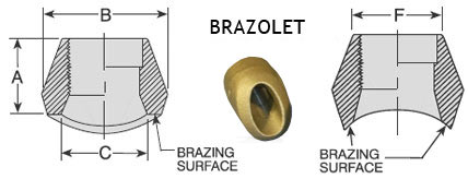
| Bronze olet for Tubing | |||||
| Type K, L, and M Tubing. ASME SB-98 UNS C65500 Alloy A | |||||
Outlet Sizes |
A |
B |
C |
Brazing Surface |
F-MIN. MIL-1183 |
1/4 |
11/16 |
1 |
9/16 |
0.188 |
0.700 |
3/8 |
13/16 |
1 1/4 |
3/4 |
0.190 |
0.855 |
1/2 |
13/16 |
1 1/4 |
3/4 |
0.190 |
0.855 |
3/4 |
1 |
1 7/16 |
7/8 |
0.220 |
1.020 |
1 |
1 1/16 |
1 3/4 |
1 1/8 |
0.240 |
1.250 |
1 1/4 |
1 1/4 |
2 1/8 |
1 7/16 |
0.270 |
1.535 |
1 1/2 |
1 5/16 |
2 9/16 |
1 3/4 |
0.300 |
1.900 |
2 |
1 3/8 |
2 7/8 |
2 |
0.330 |
2.160 |
2 1/2 |
1 1/2 |
3 1/2 |
2 9/16 |
0.360 |
2.675 |
3 |
1 13/16 |
4 1/8 |
3 |
0.384 |
3.215 |
4 |
2 1/8 |
5 1/2 |
4 5/16 |
0.437 |
4.400 |
Dimensions NPS 1/2 to 24
| NPS | A | B | C | |
| 1/2 | INCH MM | 3/4 19.05 | 1.3/8 34.93 | 15/16 23.81 |
| 3/4 | INCH MM | 7/8 22.23 | 1.3/4 44.45 | 1.3/16 30.16 |
| 1 | INCH MM | 1.1/16 26.99 | 2.1/8 53.98 | 1.7/16 36.51 |
| 1.1/4 | INCH MM | 1.1/4 31.75 | 2.9/16 65.09 | 1.3/4 44.45 |
| 1.1/2 | INCH MM | 1.5/16 33.34 | 2.7/8 73 | 2 50.80 |
| 2 | INCH MM | 1.1/2 38.10 | 3.1/2 88.90 | 2.9/16 65.09 |
| 2.1/2 | INCH MM | 1.5/8 41.28 | 4.1/16 103.19 | 3 76.20 |
| 3 | INCH MM | 1.3/4 44.45 | 4.13/16 122.24 | 3.11/16 93.66 |
| 3.1/2 | INCH MM | 1.7/8 47.63 | 5.5/8 142.88 | 4 101.60 |
| 4 | INCH MM | 2 50.80 | 6 152.40 | 4.3/4 120.65 |
| 5 | INCH MM | 2.1/4 57.15 | 7.1/16 179.39 | 5.9/16 141.29 |
| 6 | INCH MM | 2.3/8 60.3 | 8.1/2 215.90 | 6.11/16 169.86 |
| 8 | INCH MM | 2.3/4 69.85 | 10.3/8 263.53 | 8.11/16 220.66 |
| 10 | INCH MM | 3.1/16 77.79 | 12.11/16 322.26 | 10.13/16 274.64 |
| 12 | INCH MM | 3.3/8 85.73 | 14.7/8 377.83 | 12.13/16 325.44 |
| 14 | INCH MM | 3.1/2 88.90 | 16.1/8 409.58 | 14.1/16 357.19 |
| 16 | INCH MM | 3.11/16 93.66 | 18.1/4 463.55 | 16.1/16 407.99 |
| 18 | INCH MM | 3.13/16 96.84 | 20.1/2 520.70 | 18.1/16 458.79 |
| 20 | INCH MM | 4 101.60 | 22.1/2 571.50 | 20 508.00 |
| 24 | INCH MM | 4.9/16 115.89 | 27.1/8 688.98 | 24.3/16 614.36 |
| NPS | A | B | C |
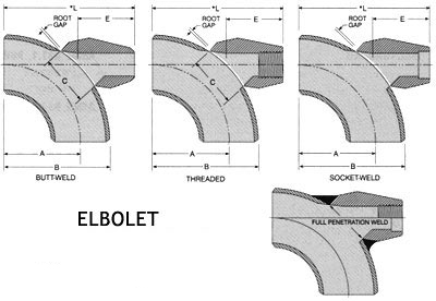
| Nominal Elbow Size Inches |
Outlet Size Inches |
Dimensions | |||
| CL 3000 Threaded & Socket Weld Std. & XS Butt-Weld |
CL 6000 Threaded & Socket Socket-Weld Sch. 160 & XXS Butt-Weld |
||||
| C | E | C | E | ||
| 36 - 3/4 | 1/4 | 1 1/2 | 1 19/32 | 1 1/2 | 1 19/32 |
| 36 - 3/4 | 3/8 | 1 1/2 | 1 19/32 | 1 1/2 | 1 19/32 |
| 36 - 3/4 | 1/2 | 1 1/2 | 1 19/32 | 1 23/32 | 1 7/8 |
| 36 - 1 | 3/4 | 1 23/32 | 1 7/8 | 2 1/4 | 2 1/4 |
| 36 - 2 | 1 | 2 1/4 | 2 1/4 | 2 7/8 | 2 1/2 |
| 36 - 2 | 1 1/4 | 2 7/8 | 2 1/2 | 3 1/8 | 2 11/16 |
| 36 - 2 | 1 1/2 | 3 1/8 | 2 11/16 | 4 3/16 | 3 1/4 |
| 36 - 3 | 2 | 4 3/16 | 3 1/4 | ||
| **2 1/2 | 4 3/16 | 3 1/4 | |||
| **3 | 5 1/16 | 3 7/8 | |||
| Order to Specific | **4 | 6 5/8 | 4 13/16 | ||
| Elbow Sizes | **6 | 9 3/8 | 6 1/2 | ** | ** |
| **8 | 13 5/16 | 8 1/16 | |||
| **10 | 17 1/32 | 10 3/8 | |||
| **12 | 19 5/8 | 11 1/8 | |||
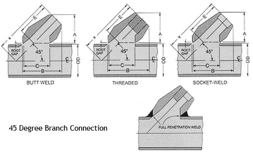
| Nominal Run Pipe Size |
Outlet Size | Dimensions | |||||||||
| CL 3000 Threaded and Socket Weld | CL 6000 Threaded and Socket Weld | ||||||||||
| A | B | C | E | A | B | C | E | ||||
| 2 1/2 - 1 1/4 | 1/4 | 1 9/16 | 2 11/32 | 1 7/16 | 1 9/16 | 1 9/16 | 2 11/32 | 1 7/16 | 1 9/16 | ||
| 12 - 3 | |||||||||||
| 2 1/2 - 1 1/4 | 3/8 | 1 9/16 | 2 11/32 | 1 7/16 | 1 9/16 | 1 9/16 | 2 11/32 | 1 7/16 | 1 9/16 | ||
| 12 - 3 | |||||||||||
| 2 1/2 - 1 1/4 | 1/2 | 1 9/16 | 2 11/32 | 1 7/16 | 1 9/16 | ||||||
| 12 - 3 | |||||||||||
| 1 1/2 - 1 1/4 | |||||||||||
| 5 - 2 | 1/2 | 1 7/8 | 2 3/4 | 1 3/4 | 1 29/32 | ||||||
| 12 - 6 | |||||||||||
| 1 1/2 - 1 1/4 | |||||||||||
| 5 - 2 | 3/4 | 1 7/8 | 2 3/4 | 1 3/4 | 1 29/32 | ||||||
| 12 - 6 | |||||||||||
| 2 1/2 - 2 | |||||||||||
| 5 - 3 | 3/4 | 2 3/16 | 3 1/4 | 2 1/8 | 2 3/16 | ||||||
| 12 - 6 | |||||||||||
| 2 1/2 - 2 | |||||||||||
| 5 - 3 | 1 | 2 3/16 | 3 1/4 | 2 1/8 | 2 3/16 | 2 1/2 | 3 21/32 | 2 5/8 | 2 15/32 | ||
| 12 - 6 | |||||||||||
| 2 1/2 - 2 | |||||||||||
| 5 - 3 | 1 1/4 | 2 1/2 | 3 27/32 | 2 5/8 | 2 15/16 | 2 3/4 | 4 7/32 | 3 1/32 | 2 5/8 | ||
| 12 - 6 | |||||||||||
| 2 1/2 - 2 | |||||||||||
| 5 - 3 | 1 1/2 | 2 3/4 | 4 7/32 | 3 1/32 | |||||||
| 12 - 6 | |||||||||||
| 5 - 4 | |||||||||||
| 8 - 6 | 1 1/2 | 3 3/8 | 5 7/16 | 4 1/8 | 3 5/32 | ||||||
| 12 - 10 | |||||||||||
| 5 - 4 | |||||||||||
| 8 - 6 | 2 | 3 3/8 | 5 7/16 | 4 1/8 | 3 5/32 | 3 3/8 | 5 7/16 | 4 1/8 | 3 5/32 | ||
| 12 - 10 | |||||||||||
| 5 - 4 | |||||||||||
| 8 - 6 | 2 1/2 | ||||||||||
| 12 - 10 | |||||||||||
| Order to Specific Run Pipe Sizes |
|||||||||||
| 3 | |||||||||||
| Order to Specific Run Pipe Sizes |
|||||||||||
| 4 | |||||||||||

| Nominal Run Pipe Size |
Outlet Size | Dimensions | ||||
| Sch. 160 and XXS Butt Weld | ||||||
| A | B | C | ||||
| 2 1/2 - 1 1/4 | 1/4 | 1 9/16 | 2 5/16 | 1 7/16 | ||
| 12 - 3 | ||||||
| 2 1/2 - 1 1/4 | 3/8 | 1 9/16 | 2 5/16 | 1 7/16 | ||
| 12 - 3 | ||||||
| 2 1/2 - 1 1/4 | 1/2 | |||||
| 12 - 3 | ||||||
| 1 1/2 - 1 1/4 | ||||||
| 5 - 2 | 1/2 | 1 13/16 | 2 3/4 | 1 3/4 | ||
| 12 - 6 | ||||||
| 1 1/2 - 1 1/4 | ||||||
| 5 - 2 | 3/4 | |||||
| 12 - 6 | ||||||
| 2 1/2 - 2 | ||||||
| 5 - 3 | 3/4 | 2 1/8 | 3 1/4 | 2 1/8 | ||
| 12 - 6 | ||||||
| 2 1/2 - 2 | ||||||
| 5 - 3 | 1 | 2 1/2 | 3 13/16 | 2 5/8 | ||
| 12 - 6 | ||||||
| 2 1/2 - 2 | ||||||
| 5 - 3 | 1 1/4 | 2 3/4 | 4 1/4 | 3 | ||
| 12 - 6 | ||||||
| 2 1/2 - 2 | ||||||
| 5 - 3 | 1 1/2 | |||||
| 12 - 6 | ||||||
| 5 - 4 | ||||||
| 8 - 6 | 1 1/2 | 3 3/8 | 5 3/8 | 4 1/8 | ||
| 12 - 10 | ||||||
| 5 - 4 | ||||||
| 8 - 6 | 2 | |||||
| 12 - 10 | ||||||
| 5 - 4 | ||||||
| 8 - 6 | 2 1/2 | |||||
| 12 - 10 | ||||||
| Order to Specific Run Pipe Sizes |
||||||
| 3 | ||||||
| Order to Specific Run Pipe Sizes |
||||||
| 4 | ||||||
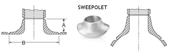
| Run Size | Outlet Size Inches |
Dimensions | |
| *A | B | ||
| 6 to 36 | 1 1/4 | 1 1/4 | 4 |
| 6 to 36 | 1 1/2 | 1 3/4 | 5 1/2 |
| 6 to 36 | 2 | 1 1/2 | 5 1/2 |
| 6 to 36 | 3 | 1 21/32 | 7 |
| 6 to 36 | 4 | 2 1/32 | 8 3/4 |
| 10 to 36 | 6 | 2 11/16 | 13 |
| 12 to 36 | 8 | 3 | 15 |
| 16 to 36 | 10 | 3 1/8 | 18 1/2 |
| 16 to 36 | 12 | 3 5/16 | 20 1/2 |
| 20 to 36 | 14 | 3 5/8 | 24 |
| 24 to 36 | 16 | 3 3/4 | 28 |
| 24 to 36 | 18 | 4 5/8 | 31 |
| 24 to 36 | 20 | 5 1/8 | 33 |
| 30 to 36 | 24 | 5 5/8 | 38 |
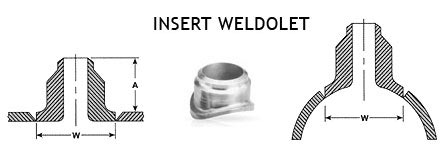
| Outlet Size |
A' Dimensions (Height above run pipe) | ||||||||||||||
| 1 1/2 | 2 | 2 1/2 | 3 | 4 | 5 | 6 | 8 | 10 | 12 | 14 | 16 | 18 | 20 | 24 | |
Std Wt Run Pipe |
1.50 | 1.50 | 1.62 | 1.75 | 2.00 | 2.25 | 2.38 | 2.75 | 3.06 | 3.38 | 3.50 | 3.75 | 3.81 | 4 | 4.56 |
XS Run Pipe |
1.50 | 1.50 | 1.62 | 1.75 | 2.00 | 2.25 | 3.06 | 3.87 | 3.69 | 4.06 | 3.81 | 4.19 | 4.38 | 4.69 | 5.50 |
.500" to .750" Thick Run Pipe |
- | - | - | 2.88 | 3.31 | 3.75 | 4.12 | 4.18 | 4.25 | 4.37 | 4.50 | 4.69 | 5.13 | 5.62 | 6.50 |
.750" to 1.00" Thick Run Pipe |
- | - | - | 3.22 | 3.38 | 3.75 | 4.34 | 4.62 | 4.84 | 5.10 | 5.25 | 5.88 | 6.50 | 6.75 | 7.62 |
1.00" to 1.25" Thick Run Pipe |
- | - | - | 3.38 | 3.50 | 4.00 | 4.50 | 4.88 | 5.00 | 5.38 | 5.50 | 6.00 | 6.50 | 7.00 | 8.00 |
1.25" to 1.50" Thick Run Pipe |
- | - | - | 3.62 | 3.87 | 4.25 | 4.69 | 5.16 | 5.31 | 5.68 | 5.81 | 6.44 | 6.50 | 7.56 | 8.72 |
|
|||||||||||||||
| Outlet Size |
*'W' Dimensions (Max. O.D. of fitting - Max. size of hole) | ||||||||||||||
| 1 1/2 | 2 | 2 1/2 | 3 | 4 | 5 | 6 | 8 | 10 | 12 | 14 | 16 | 18 | 20 | 24 | |
Std Wt Run Pipe |
3.50 | 4.25 | 4.88 | 5.69 | 7.00 | 8.06 | 9.71 | 11.71 | 14.00 | 16.32 | 17.56 | 19.75 | 22.00 | 24.00 | 29.00 |
| XS Run Pipe | 3.56 | 4.38 | 5.00 | 5.75 | 7.12 | 8.25 | 10.44 | 13.44 | 14.25 | 16.56 | 18.00 | 20.00 | 22.44 | 25.00 | 30.32 |
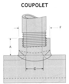
| 300# Female Threaded Coupling olet | |||
| Nominal Outlet Size |
Dimensions | ||
| A | C | F | |
| 1/2 | 15/16 | 0.745 | 1.188 |
| 3/4 | 1 | 0.958 | 1.441 |
| 1 | 1 3/16 | 1.188 | 1.562 |
| 1 1/4 | 1 5/16 | 1.550 | 1.906 |
| 1 1/2 | 1 9/16 | 1.780 | 2.188 |
| 2 | 1 11/16 | 2.260 | 2.750 |
| 2 1/2 | 1 13/16 | 2.890 | 3.386 |
| 3 | 2 1/2 | 3.400 | 4.000 |
| 4 | 3 | 4.380 | 5.000 |
| Interchangeability or Combination of Sizes | ||||||||||
| Coupling olet Size Inches |
Run Sizes | |||||||||
| 1/2 | 1/2 | 3/4 | 1 1/4 -1 | 8-3 | 36-10 | |||||
| 3/4 | 3/4 | 1 | 2 - 1 1/4 | 36-8 | ||||||
| 1 | 1 | 1 1/4 | 2 - 1 1/2 | 8-5 | 36-10 | |||||
| 1 1/4 | 1 1/4 | 1 1/2 | 2 1/2 - 2 | 8-5 | 36-10 | |||||
| 1 1/2 | 1 1/2 | 2 | 2 1/2 | 8-5 | 16-10 | 36-18 | ||||
| 2 | 2 | 2 1/2 | 3 | 4 | 5 | 6 | 8 | 10 | 16-12 | 36-18 |
| 2 1/2 | 2 1/2 | 3 | 3 1/2 | 5 | 6 | 8 | 12-10 | 16-14 | 36-18 | |
| 3 | 3 | 3 1/2 | 4 | 6 | 8 | 10 | 12 | 14 | 18-16 | 36-20 |
| 4 | 5 | 6 | 8 | 14-12 | 16 | 18 | 20 | 24 | 36 | |
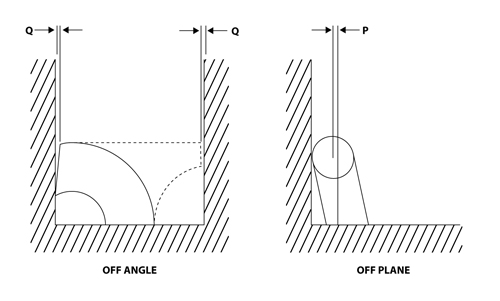
| DIMENSIONAL TOLERANCES OF FITTINGS (In mm) | |||||||||||||||||||||||||||||||||||||||||||||||||||||||||||||||||||||||||||||||||||||||||||||||||||||||||
|
|||||||||||||||||||||||||||||||||||||||||||||||||||||||||||||||||||||||||||||||||||||||||||||||||||||||||
|
|
|
|
|
|
|
|
|
|
|
|
|
|
|
|
|
|
|
|
|
|
|
|
|
|
|
|
|
|
|
|
|
|
|
|
|
|
|
|
|
|
|
|
|
|
|
|
|
|
|
|
|
|
|
|
|
|
|
|
|
|
|
|
|
|
|
|
|
|
|
|
|
|
|
|
|
|
|
|
|
|
|
|
|
|
|
|
|
|
|
|
|
|
|
|
|
|
|
|
|
|
|
|
|
|
|
|
|
|
|
|
|
|
|
|
|
|
|
|
|
|
|
|
|
|
|
|
|
|
|
|
|
|
|
|
|
|
|
|
|
|
|
|
|
|
|
|
|
|
|
|
|
|
|
|
|
|
|
|
|
|
|
|
|
|
|
|
|
|
|
|
|
|
|
|
|
|
|
|
|
|
|
|
|
|
|
|
|
|
|
|
|
|
|
|
|
|
|
|
|
|
|
|
|
|
|
|
|
|
|
|
|
|
|
|
|
|
|
|
|
|
|
|
|
|
|
|
|
|
|
|
|
|
|
|
|
|
|
|
|
|
|
|
|
|
|
|
|
|
|
|
|
|
|
|
|
|
|
|
|
|
|
|
|
|
|
|
|
|
|
|
|
|
|
|
|
|
|
|
|
|
|
|
|
|
|
|
|
|
|
|
|
|
|
|
|
|
|
|
|
|
|
|
|
|
|
|
|
|
|
|
|
|
|
|
|
|
|
|
|
|
|
|
|
|
|
|
|
|
|
|
|
|
|
|
|
|
|
|
|
|
|
|
|
|
|
|
|
|
|
|
|
|
|
|
|
|
|
|
|
|
|
|
|
|
|
|
|
|
|
|
|
|
|
|
|
|
|
|
|
|
|
|
|
|
|
|
|
|
|
|
|
|
|
|
|
|
|
|
|
|
|
|
|
|
|
|
|
|
|
|
|
|
|
|
|
|
|
|
|
|
|
|
|
|
|
|
|
|
|
|
|
|
|
|
|
|
|
|
|
|
|
|
|
|
|
|
|
|
|
|
|
|
|
|
|
|
|
|
|
|
|
|
|
|
|
|
|
|
|
|
|
|
|
|
|
|
|
|
|
|
|
|
|
|
|
|
|
|
|
|
|
|
|
|
|
|
|
|
|
|
|
|
|
|
|
|
|
|
|
|
|
|
|
|
|
|
|
|
|
|
|
|
|
|
|
|
|
|
|
|
|
|
|
|
|
|
|
|
|
|
|
|
|
|
|
|
|
|
|
|
|
|
|
|
|
|
|
|
|
|
|
|
|
|
|
|
|
|
|
|
|
|
|
|
|
|
|
|
|
|
|
|
|
|
|
|
|
|
|
|
|
|
|
|
|
|
|
|
|
|
|
|
|
|
|
|
|
|
|
|
|
|
|
|
|
|
|
|
|
|
|
|
|
|
|
|
|
|
|
|
|
|
|
|
|
|
|
|
|
|
|
|
|
|
|
|
|
|
|
|
|
|
|
|
|
|
|
|
|
|
|
|
|
|
|
|
|
|
|
|
|
|
|
|
|
|
|
|
|
|
|
|
|
|
|
|
|
|
|
|
|
|
|
|
|
|
|
|
|
|
|
|
|
|
|
|
|
|
|
|
|
|
|
|
|
|
|
|
| Standard of Country | Chemical Composition | |||||||||||
| USA | German | UK | Japan | C Max | SI Max | Mn Max | P max | S Max | Ni | Cr | Mo | |
| AISI | W-Nr | DIN | BS | JIS | ||||||||
| 301 | 1.4310 | X12Cr Ni 177 | 301S21 | SUS 301 | 0.15 | 1 | 2 | 0.045 | 0.03 | 6.00-8.00 | 16.00-18.00 | - |
| 304 | 1.4301 | XDCr Ni 189 | 304S16 | SUS304 | 0.08 | 1 | 2 | 0.045 | 0.03 | 8.00-10.50 | 18.00-20.00 | - |
| 304L | 1.4306 | X3Cr Ni 89 | 304S12 | SUS 304L | 0.03 | 1 | 2 | 0.045 | 0.03 | 9.00-13.00 | 18.00-20.00 | - |
| 305 | 1.4303 | X5Cr Ni 1911 | 305S19 | SUS 305 | 0.12 | 1 | 2 | 0.045 | 0.03 | 10.50-13.00 | 17.00-19.00 | - |
| 310S | 1.4841 | X 15 Cr Ni Si 2520 | 310S24 | SUS 310S | 0.08 | 1.5 | 2 | 0.045 | 0.03 | 19.00-22.00 | 24.00-26.00 | - |
| 316 | 1.4401 | X15 Cr Ni Mo 1810 | 306S16 | SUS 316 | 0.08 | 1 | 2 | 0.045 | 0.03 | 10.00-14.00 | 16.00-18.00 | 2.00-3.00 |
| 316L | 1.4435 | X15 Cr Ni Mo 1812 | 306S12 | SUS 316 L | 0.03 | 1 | 2 | 0.045 | 0.03 | 12.00-15.00 | 16.00-18.00 | 2.00-3.00 |
| 430 | 1.4016 | X8Cr 17 | 430S17 | SUS 430 | 0.12 | 0.75 | 1 | 0.04 | 0.03 | 0.6 | 16.00-18.00 | - |
| 434 | 1.4113 | - | - | SUS 434 | 0.12 | 1 | 1 | 0.04 | 0.03 | 0.6 | 16.00-18.00 | 0.75-1.25 |
| 410 | 1.4006 | X10 Cr 13 | 410S21 | SUS 410 | 0.15 | 1 | 1 | 0.04 | 0.03 | 0.6 | 11.50-13.50 | - |
| 420 | 1.4021 | X 20 Cr 13 | 420S29 | SUS 420 J1 | 0.16-0.25 | 1 | 1 | 0.04 | 0.03 | 0.6 | 12.00-14.00 | - |
| 420 | 1.4034 | X 40 Cr 13 | 420S45 | SUS 420 J2 | 0.26 - 0.40 | 1 | 1 | 0.04 | 0.03 | 0.6 | 12.00-14.00 | - |
| USA | German | UK | Japan | Tensile test(min) | Hardness (Max) | |||||||
| AISI | W-Nr | DIN | BS | JIS | Y/S | T/S | Elongat-ion | HB | HRB | Hv | ||
| kg/mm2 | N/mm2 | kgf/mm2 | N/mm2 | |||||||||
| 301 | 1.4310 | X12Cr Ni 177 | 301S21 | SUS 301 | 21 | 206 | 53 | 520 | 40 | 187 | 90 | 200 |
| 304 | 1.4301 | XDCr Ni 189 | 304S16 | SUS304 | 21 | 206 | 53 | 520 | 40 | 187 | 90 | 200 |
| 304L | 1.4306 | X3Cr Ni 89 | 304S12 | SUS 304L | 18 | 177 | 49 | 481 | 40 | 187 | 90 | 200 |
| 305 | 1.4303 | X5Cr Ni 1911 | 305S19 | SUS 305 | 18 | 177 | 49 | 481 | 40 | 187 | 90 | 200 |
| 310S | 1.4841 | X 15 Cr Ni Si 2520 | 310S24 | SUS 310S | 21 | 206 | 53 | 520 | 40 | 187 | 90 | 200 |
| 316 | 1.4401 | X15 Cr Ni Mo 1810 | 306S16 | SUS 316 | 21 | 206 | 53 | 520 | 40 | 187 | 90 | 200 |
| 316L | 1.4435 | X15 Cr Ni Mo 1812 | 306S12 | SUS 316 L | 18 | 177 | 49 | 481 | 40 | 187 | 90 | 200 |
| 430 | 1.4016 | X8Cr 17 | 430S17 | SUS 430 | 21 | 206 | 46 | 451 | 22 | 183 | 88 | 200 |
| 434 | 1.4113 | - | - | SUS 434 | 21 | 206 | 46 | 451 | 22 | 183 | 88 | 200 |
| 410 | 1.4006 | X10 Cr 13 | 410S21 | SUS 410 | 21 | 206 | 45 | 441 | 20 | 200 | 93 | 210 |
| 420 | 1.4021 | X 20 Cr 13 | 420S29 | SUS 420 J1 | 23 | 226 | 53 | 520 | 18 | 223 | 97 | 234 |
| 420 | 1.4034 | X 40 Cr 13 | 420S45 | SUS 420 J2 | 23 | 226 | 55 | 539 | 18 | 235 | 99 | 247 |
| Werkstoff Nr. | DIN / DIN EN | AISI USA | UNS Unified | SS Swedish | AFNOR French | BS British |
| 1.4000 | X6 Cr 13 | 410 S | S 41008 | 2301 | Z 8 C 12 | 403 S 17 |
| 1.4002 | X6 CrAI 13 | 405 | S 40500 | Z 8 CA 12 | 405 S 17 | |
| 1.4003 | X2 CrNi 12 | |||||
| 1.4005 | X12 CrS 13 | 416 | S 41600 | 2380 | Z 11 CF 13 | 416 S 21 |
| 1.4006 | X12 Cr 13 | 410 | S 41000 | 2302 | Z 10 C 13 | 410 S 21 |
| 1.4016 | X6 Cr 17 | 430 | S 43000 | 2320 | Z 8 C 17 | 430 S 15 |
| 1.4021 | X20 Cr 13 | 420 | S 42000 | 2303 | Z 20 C 13 | 420 S 37 |
| 1.4024 | X 15 Cr 13 | -410 | (S 41000) | 420 S 29 | ||
| 1.4028 | X30 Cr 13 | 420 F | S 42020 | 2304 | Z 30 C 13 | 420 S 45 |
| 1.4031 | X39 Cr 13 | 2304 | Z 33 C 13 | 420 S 45 | ||
| 1.4034 | X46 Cr 13 | 2304 | Z 40 C 14 | (420 S 45) | ||
| 1.4057 | X17 CrNi 16-2 | 431 | S 43100 | 2321 | Z 15 CN 16,02 | 431 S 29 |
| 1.4104 | X14 CrMoS 17 | 430 F | S 43020 | 2383 | Z 13 CF 17 | (441 S 29) |
| 1.4112 | X90 CrMoV 18 | 440 B | S 44003 | |||
| 1.4113 | X6 CrMo 17-1 | 434 | S 43400 | Z 8 CD 17-01 | 434 S 17 | |
| 1.4120 | X20 CrMo 13 | Z 20 CD 14 | ||||
| 1.4122 | X39 CrMo 17-1 | |||||
| 1.4301 | X5 CrNi 18-10 | 304 | S 30400 | 2332 | Z 6 CN 18,09 | 304 S 15 |
| 1.4303 | X4 CrNi 18-12 | -305 | (S 30500) | Z 8 CN 18-12 | 305 S 19 | |
| 1.4305 | X8 CrNiS 18-9 | 303 | S 30300 | 2346 | Z 8 CNF 18,09 | 303 S 31 |
| 1.4306 | X2 CrNi 19-11 | 304 L | S 30403 | 2352 | Z 2 CN 18,09 | 304 S 11 |
| 1.4307 | X2 CrNi 18-9 | 304 L | 2352 | Z 3 CN 18,10 | 304 S 11 | |
| 1.4310 | X10 CrNi 18-8 | 301 | S 30100 | 2331 | Z 12 CN 18,08 | 301 S 22 |
| 1.4311 | X2 CrNiN 18-10 | 304 LN | S 30453 | 2371 | Z 3 CN 18-10 AZ | 304 S 61 |
| 1.4313 | X3 CrNiMo 13-4 | CA 6 NM | 2384 | Z 4 CND 13,04 M | 425 C 11 | |
| 1.4315 | X5 CrNiN 19-9 | 304 N | S 30451 | Z 6 CN 19-09 AZ | ||
| 1.4318 | X2 CrNiN 18-7 | 301 LN | ||||
| 1.4319 | X 5 CrNi 18 7 | 302 | 23 31 | Z 10 CN 18-09 | 302S25 | |
| 1.4401 | X5 CrNiMo 17-12-2 | 316 | S 31600 | 2347 | Z 7 CND 17,12,02 | 316 S 31 |
| 1.4404 | X2 CrNiMo 17-12-2 | 316 L | S 31603 | 2348 | Z 3 CND 18,12,02 | 316 S 11 |
| 1.4406 | X 2 CrNiMoN 17 12 2 | Z 2 CND 17-12-Az | ||||
| 1.4418 | X4 CrNiMo 16-5-1 | 2387 | Z 6 CND 16,05,01 | |||
| 1.4427 | X4 CrNiMoS 18-11 | 316 F | S 31620 | |||
| 1.4429 | X2 CrNiMoN 17-13-3 | 316 LN | S 31653 | 2375 | Z 3 CND 17-12 AZ | 316 S 63 |
| 1.4432 | X2 CrNiMo 17-12-3 | 316 L | 2353 | Z 3 CND 17,12,03 | 316 S 13 | |
| 1.4435 | X2 CrNiMo 18-14-3 | 316 L | S 31603 | 2353 | Z 3 CND 18,14,03 | 316 S 11 |
| 1.4436 | X3 CrNiMo 17-13-3 | 316 | S 31600 | 2343 | Z 7 CND 18,12,03 | 316 S 31 |
| 1.4438 | X2 CrNiMo 18-15-4 | 317 L | S 31703 | 2367 | Z 3 CND 19,15,04 | 317 S 12 |
| 1.4439 | X2 CrNiMoN 17-13-5 | (317 LMN) | ||||
| 1.4449 | X5 CrNiMo 17-13 | 317 | S 31700 | 317 S 16 | ||
| 1.4460 | X3 CrNiMoN 27-5-2 | 329 | S 32900 | 2324 | Z 5 CND 27.05.AZ | |
| 1.4462 | X2 CrNiMoN 22-5-3 | S 31803 | 2377 | (Z 5 CNDU 21,08) | ||
| 1.4465 | X1 CrNiMoN 25-25-2 | Z 2 CND 25-22 AZ | ||||
| 1.4501 | X 3 CrNiMoN 25 7 | UNS32760 | Z 3 CND 25-06Az | |||
| 1.4509 | X2 CrTiNb 18 | 441 | Z 3 CTNb 18 | |||
| 1.4510 | X3 CrTi17 | 439 | S 43900 | Z 4 CT 17 | ||
| 1.4511 | X8 CrNb 17 | Z 4 CNb 17 | ||||
| 1.4512 | X2 CrTi 12 | 409 | S 40900 | Z 3 CT 12 | 409 S 19 | |
| 1.4520 | X2 CrTi 17 | |||||
| 1.4521 | X2 CrMoTi 18-2 | 444 | S 44400 | |||
| 1.4529 | X1 NiCrMoCuN 25-20-7 | (S 31254) | ||||
| 1.4539 | X1 NiCrMoCu 25-20-5 | (904 L) | N 08904 | 2562 | Z 1 NCDU 25,20 | |
| 1.4541 | X6 CrNiTi 18-10 | 321 | S 32100 | 2337 | Z 6 CNT 18,10 | 321 S 31 |
| 1.4542 | X5 CrNiCuNb 16-4 | 630 | S 17400 | Z 67CNU 15,05 | ||
| 1.4544 | ||||||
| 1.4546 | X5 CrNiNb 18-10 | |||||
| 1.4550 | X6 CrNiNb 18-10 | 347 | S 34700 | 2338 | Z 6 CNNb 18,10 | 347 S 31 |
| 1.4561 | X1 CrNiMoTi 18-13-2 | 316 Ti | S 31603 | |||
| 1.4563 | X1 NiCrMoCu 31-27-4 | N 08028 | 2584 | Z 2 NCDU 31,27 | ||
| 1.4565 | X2 CrNiMnMoNbN 25-18 -5-4 | S 34565 | ||||
| 1.4568 | X7 CrNiAI 17-7 | 631 | S 17700 | 2388 | Z 9 CNA 17-07 | |
| 1.4571 | X6 CrNiMoTi 17-12-2 | 316 Ti | S 31635 | 2350 | Z 6 CNDT 17,12 | 320 S 31 |
| 1.4573 | X 10 CrNiMoTi 18 12 | 320S33 | ||||
| 1.4580 | X 6 CrNiMoNb 17 12 2 | Z 6 CNDNb 17-12 | ||||
| 1.4583 | X 10 CrNiMoNb 18 12 | |||||
| 1.4589 | X5 CrNiMoTi 15-2 | |||||
| 1.4713 | X10 CrAISi 7 | Z 8 CA 7 | ||||
| 1.4724 | X 10 CrAl 13 | (Z 10 C 13) | ||||
| 1.4742 | X 10 CrAl 18 | Z 10 CAS 18 | ||||
| 1.4762 | X 10 CrAl 24 | (446) | (S 44600) | (2322) | Z 10 CAS 24 | |
| 1.4821 | X 20 CrNiSi 25 4 | Z 20 CNS 25.04 | ||||
| 1.4828 | X 15 CrNiSi 20 12 | 309 | (S 30900) | Z 15 CNS 20.12 | 309 S 24 | |
| 1.4841 | X 15 CrNiSi 25 20 | 314 | S 31400 | Z 12 CNS 25.20 | 314 S 25 | |
| 1.4842 | X 12 CrNi 25 20 | 310 S | 23 61 | Z 12 CN 25-20 | ||
| 1.4845 | X 12 CrNi 25 21 | 310 S | S 31008 | 2361 | Z 12 CN 25.20 | 310 S 24 |
| 1.4864 | X 12 NiCrSi 36 16 | 330 | N 08330 | Z 12 CNS 35.16 | (3076 NA 17) | |
| 1.4876 | X 10 NiCrAlTi 32 20 | B 163 | Z 8 NC 32.21 | 3076 NA 15 H | ||
| 1.4878 | X 12 CrNiTi 18 9 | 321 | S 32100 | 2337 | Z 6 CNT 18.12 | 321 S 51 |
| 1.4939 | 904L | Z 12 CNDV 12-02 |
A53/A53M-07 Standard Specification for Pipe, Steel, Black and Hot-Dipped, Zinc-Coated, Welded and Seamless
A105/A105M-05 Standard Specification for Carbon Steel Forgings for Piping Applications
A106-106M-08 Standard Specification for Seamless Carbon Steel Pipe for High-Temperature Service
A179/A179M-90a (2005) Standard Specification for Seamless Cold-Drawn Low-Carbon Steel Heat-Exchanger and Condenser Tubes
A181/A181M-06 Standard Specification for Carbon Steel Forgings, for General-Purpose Piping
A182/A182M-08a Standard Specification for Forged or Rolled Alloy-Steel Pipe Flanges, Forged Fittings, and Valves and Parts for High-Temperature Service
A193/A193M-08b Standard Specification for Alloy- Steel and Stainless Steel Bolting Materials for High-Temperature Service
A194/A194M-08b Standard Specification for Carbon and Alloy Steel Nuts for Bolts for High- Pressure or High-Temperature Service, or Both
A213/A213M-08 Standard Specification for Seamless Ferritic and Austenitic Alloy-Steel Boiler, Superheater, and Heat-Exchanger Tubes
A240/A240M-08 Standard Specification for Heat-Resisting Chromium and Chromium-Nickel Stainless Steel Plate, Sheet, and Strip for Pressure Vessels
A249/A249M-08 Standard Specification for Welded Austenitic Steel Boiler, Superheater, Heat- Exchanger, and Condenser Tubes
A268/A268M-05a Standard Specification for Seamless and Welded Ferritic and Martensitic Stainless Steel Tubing for General Service
A269-08 Standard Specification for Seamless and Welded Austenitic Stainless Steel Tubing for General Service
A270-03a Standard Specification for Seamless and Welded Austenitic Stainless Steel Sanitary Tubing
A276-08a Standard Specification for Stainless Steel Bars and Shapes
A312/A312M-08a Standard Specification for Seamless and Welded Austenitic Stainless Steel Pipes
A335/A335M-06 Standard Specification for Seamless Ferritic Alloy-Steel Pipe for High- Temperature Service
A351/A351M-06 Standard Specification for Castings, Austenitic, for Pressure-Containing Parts
A358/A358M-08 Standard Specification for Electric- Fusion-Welded Austenitic Chromium-Nickel Alloy Steel Pipe for High-Temperature Service
A376/A376M-06 Standard Specification for Seamless Austenitic Steel Pipe for High- Temperature Central-Station Service
A403/A403M-07 Standard Specification for Wrought Austenitic Stainless Steel Piping Fittings
A409/A409M-08 Standard Specification for Welded Large Diameter Austenitic Steel Pipe for Corrosive or High-Temperature Service
A450/A450M-07 Standard Specification for General Requirements for Carbon, Ferritic Alloy, and Austenitic Alloy Steel Tubes
A479/A479M-08 Standard Specification for Stainless Steel Bars and Shapes for Use in Boilers and Other Pressure Vessels
A511-511M-08 Standard Specification for Seamless Stainless Steel Mechanical Tubing
A554-08 Standard Specification for Welded Stainless Steel Mechanical Tubing
A564/A564M-04 Standard Specification for Hot- Rolled and Cold-Finished Age-Hardening Stainless Steel Bars and Shapes
A789/A789M-08a Standard Specification for Seamless and Welded Ferritic/Austenitic Stainless Steel Tubing for General Service
A790/A790M-08 Standard Specification for Seamless and Welded Ferritic/Austenitic Stainless Steel Pipe
A815/A815M-08a Standard Specification for Wrought Ferritic, Ferritic/Austenitic, and Martensitic Stainless Steel Piping Fittings
B68-02 Standard Specification for Seamless Copper Tube, Bright Annealed
B75-99 Standard Specification for Seamless Copper Tube
B88M-05 Standard Specification for Seamless Copper Water Tube
B160-05 Standard Specification for Nickel Rod and Bar
B161-05 Standard Specification for Nickel Seamless Pipe and Tube
B162-99 Standard Specification for Nickel Plate, Sheet, and Strip
B163-08a Standard Specification for Seamless Nickel and Nickel Alloy Condenser and Heat- Exchanger Tubes
B164-08 Standard Specification for Nickel-Copper Alloy Rod, Bar, and Wire
B165-05 Standard Specification for Nickel-Copper Alloy (UNS N04400)* Seamless Pipe and Tube
B166-08 Standard Specification for Nickel-Chromium-Iron Alloys (UNS N06600, N06601, N06603, N06690, N06025, and N06045)* and Nickel-Chromium-Cobalt-Molybdenum Alloy (UNS N06617) Rod, Bar, and Wire
B366-04b Standard Specification for Factory- Made Wrought Nickel and Nickel Alloy Fittings
B407-08a Standard Specification for Nickel-Iron- Chromium Alloy Seamless Pipe and Tube
B408-06 Standard Specification for Nickel-Iron- Chromium Alloy Rod and Bar
B514-05 Standard Specification for Welded Nickel-Iron-Chromium Alloy Pipe
B725-05 Standard Specification for Welded Nickel (UNS N02200/UNS N02201) and Nickel Copper Alloy (UNS N04400) Pipe
B775-08 Standard Specification for General Requirements for Nickel and Nickel Alloy Welded Pipe
Nickel AMS Aerospace Specifications
| Alloy | UK | USA | Germany | France | Europe | Manufacturers Specifications | Company |
| Alloy 25 | BS HR40 | WL 2.4967 | KC20WN | MSRR 7052 | Rolls-Royce | ||
| WL 2.4464 | |||||||
| Alloy 75 | BS HR5 | WL 2.4630 | NC20T | EN 2306 | MSRR 7004 | Rolls-Royce | |
| WL 2.4951 | |||||||
| Alloy 80A | BS HR1 | WL 2.4631 | NC20TA | MSRR 7011 | Rolls-Royce | ||
| BS HR601 | WL 2.4952 | ||||||
| Alloy 90 | BS HR2 | WL 2.4632 | NCK20TA | MSRR 7137 | Rolls-Royce | ||
| Alloy C263 | BS HR10 | AMS 5886 | WL 2.4650 | NCK20D | EN 2199 | MSRR 7035 | Rolls-Royce |
| AMS 5872 | |||||||
| Alloy C263 | AMS 5750 | WL 2.4819 | ND16C15 | ||||
| Alloy 400 | NA13 | AMS 4675 | WL 2.4360 | ||||
| Alloy 625 | NA21 | AMS 5666 | WL 2.4856 | NC22DNb | |||
| AMS 5599 | |||||||
| Alloy 718 | AMS 5662 | WL 2.4668 | NC19FeNb | MSRR 7115 | Rolls-Royce | ||
| AMS 5663 | |||||||
| AMS 5596 | |||||||
| Alloy K500 | NA18 | AMS 4676 | WL 2.4374 | ||||
| Alloy X750 | AMS 5542, AMS 5667 | WL 2.4669 | NC15FeTNbA | MSRR 7244 | Rolls-Royce | ||
| Alloy X | AMS 5754 | WL 2.4665 | NC22FeD | MSRR 7127 | Rolls-Royce | ||
| Waspaloy | AMS 5706 | NC20K14 | MSRR 7192 | Rolls-Royce |
Colbalt Alloys AMS standards and specifications
| Alloy | UK | USA | Germany | France | Europe | Manufacturers Specifications | Company |
| L-605 (Cobalt Alloy) | AMS 5759 | ||||||
| MP-159 (Cobalt Alloy) | AMS 5842 | ||||||
| MP-35N (Cobalt Alloy) | AMS 5844-5 |
Pure Nickel alloys AMS standards and specifications
| UNS | alloy | alloy-no. | short term | ASTM | ASME | SAE AMS | AFNOR (F) | BS (UK) | ATI Allvac | Thyssen- Krupp VDM | Special Metals (Alloy name) | Haynes | Böhler Marke |
| PURE NICKEL AMS STANDARDS | |||||||||||||
| N02200 | alloy 200 | 2.4060 /2.4066 | Ni 99.2 | B 160-163, B 366, 564, 725, 730, 751, 775, 829 | SB 160-163, 366, 564, 725, 730, 751, 775, 829 | 5553 | 3072-3076 (NA 11) | Nickel 99.2 | Nickel 200 | L 200 | |||
| N02201 | alloy 201 | 2.4068 | LC-Ni 99 | B 160-163, B 366, 725, 730, 751, 775, 829 | SB 160-163, 366, 564, 725, 730, 751, 775, 829 | 5553 | 3072-3076 (NA 12) | LC-Nickel 99.2 | Nickel 201 | L 200 | |||
| N02205 | alloy 205 | 2.4061 | LC-Ni 99.6 | F 1, F 3 | 5555 | LC-Nickel 99.6 | Nickel 205 | ||||||
| N02270 | alloy 270 | 2.4050 | Ni 99.8 | F1, F 3 | Nickel 270 | ||||||||
| N03300 | F 290 | Nickel 300 | |||||||||||
| N03301 | alloy 301 | - | Ni 93 | Duranickel 301 | |||||||||
| N02061 | alloy 61 | 2.4155 | NiTi4 | NA 32 | Nickel S 9604 - FM 61 | Nickel 61 | |||||||
| NICKEL-COPPER AMS STANDARDS | |||||||||||||
| N04400 | alloy 400 | 2.4360 / 2.4366 | NiCu30Fe | B 127, 163-165, 366, 564, 725, 730, 751, 775, 829 | SB 127, 163-165 B 366, 564, 725, 730, 751, 775, 829 | 4544, 4574, 4575, 4675, 4730, 4731 | NU 30 | 3072-3076 NA 13 | ATI 400 | Nicorros 400 | Monel 400 | L 322 | |
| N04405 | alloy 405 | 2.4363 | NiCu30Fe Mn | B 127, 164 | SB 164 | 7234, 4674 | Monel R-405 | ||||||
| N05500 | alloy K-500 | 2.4375 | NiCu30Al | B 865 | SB 865 | 4676 | NU 30 AT | 3072-3076 (NA 18) | ATI K-500 | Nicorros Al | Monel K-500 | ||
| N04060 | 2.4377 | SG-NiCu 30Mn | NA 33 | Nicorros S 6530- FM 60 | Monel 60 | ||||||||
| NICKEL-CHROMIUM AMS STANDARDS | |||||||||||||
| N06002 | alloy X | 2.4665 | NiCr22Fe 18Mo | B 366, 435, 572, 619, 622, 626, 751, 775, 829 | SB 366, 435, 572, 619, 622, 626, 751, 775, 829 | 5536, 5587, 5588, 5754, 5798 | NC 22 FeD | HR 6, HR 204 | ATI H-X | Nicrofer 4722 Co | Inconel HX | Hastelloy X | L 329 |
| N06003 | alloy 80/20 | 2.4869 | NiCr80-20 | B 344 | Cronix 80 | Resistohm 80 Brightray C/S | |||||||
| N06004 | alloy 60/40 | 2.4867 | NiCr60-15 | B 344 | Resistohm 60 Brightray B | ||||||||
| N06008 | alloy 70/30 | 2.4658 | NiCr70-30 | Cronix 70 | Resistohm 70 | ||||||||
| N06025 | alloy 602 | 2.4633 | NiCr25 FeAlY | Nicrofer 6025 HT, 602CA | |||||||||
| N06030 | alloy G-30 | 2.4603 | NiCr30Fe 15Mo | B 582, 619, 622, 626 | SB 582, 619, 622, 626 | NC 22 FeD | Hastelloy G-30 | ||||||
| N06045 | alloy 45 TM | 2.4889 | NiCr28Fe SiCe | Nicrofer 45 TM | |||||||||
| N06075 | alloy 75 | 2.4630 / 2.4951 | NiCr20Ti | NC 20 T | HR 5, 203, 403, 504 | Nicrofer 7520 | Nimonic 75 | Haynes 75 | |||||
| N06082 | alloy 82 | 2.4806 | SG-NiCr 20Nb | 2901 NA 35 | Nicrofer S 7020 | Inconel 82 | |||||||
| N06230 | alloy 230 | 2.4733 | NirCr22W 14Mo | B 435, 619, 622 | SB 435, 619, 622 | 5878, 5891 | Haynes 230 | ||||||
| N06333 | alloy 333 | 2.4608 | NiCr26 MoW | 5593, 5717 | Nicrofer 4626W / S 4626 | ||||||||
| N06600 | alloy 600 H | 2.4816 | NiCr15Fe | B 166-168, 366, 516, 517, 564, 751, 775, 829, 163 | SB 163, 166-168, 366, 516, 517, 564, 751, 775, 829 | 5540, 5580, 5665, 5687 | NC 15 Fe | 3072-3076 (NA 14) | ATI 600 | Nicrofer 7216 / 7216 H | Inconel 600 | L312 | |
| N06601 | alloy 601 | 2.4851 | NiCr23Fe | B 166-168, 751, 775, 829, 163 | SB 166-168, 751, 775, 829 | 5715, 5870 | NC 23Fe A | ATI 601 | Nicrofer 6023 | Inconel 601 | |||
| N06602 | alloy 600 L | 2.4817 | LC-NiCr 15Fe | B 163, 167, 516, 517 | Nicrofer 7216 LC | Inconel 602 | |||||||
| N06603 | - | 2.4647 | NiCr25Fe AlYC | B 166, 517 | Nicrofer 6125 GT/ 603 GT | ||||||||
| N06617 | alloy 617 | 2.4663 | NiCr23Co 12Mo | B 166, 167, 168, 546, 564 | SB 166, 168, 546, 564 | 5887-5889 | Nicrofer 5520 Co | Inconel 617 | Haynes 617 | ||||
| N06690 | alloy 690 | 2.4642 | NiCr29Fe | B 166-168, 163, 564, 751, 775, 829 | SB 163, 166-168, 564, 829 | NC 30 Fe | ATI 690 | Nicrofer 6030 | Inconel 690 | ||||
| N06693 | alloy 693 | - | NiCr29 | B 168, 168 | Inconel 693 | ||||||||
| N06950 | alloy G-50 | NiCr20Fe 18Mo | Inconel 050 | Hastelloy G-50 | |||||||||
| N07001 | Waspa- loy | 2.4654 | NiCr19Co 14Mo | B 637 | 5544, 5704, 5706-5709, 5828 | NC20 H14 | Waspaloy | Waspaloy | L303 | ||||
| N07041 | alloy 41 | 2.4973 | NiCr19Co 11Mo | 5545, 5712, 5413, 5800 | NC 19 KDT | ATI Rene 41 | Udimet R41 | Haynes R-41 | |||||
| N07080 | alloy 80 A | 2.4952 / 2.4631 | NiCr20TiAl | B 637 | NC 20 TA | HR1, 201, 401, 601, BS 3076 (NA 20) | ATI 80 A | Nicrofer 7520 Ti | Nimonic 80A | L 306, L 080 A | |||
| N07090 | alloy 90 | 2.4632 / 2.4969 | NiCr20Co 18Ti | - | 5829 | NCK 20 D | HR2, 202, 402, 501-503 | ATI N-90 | Nimonic 90 | ||||
| N07214 | alloy 214 | 2.4646 | NiCr16Al4 Fe3 | Haynes 214 | |||||||||
| N07263 | alloy C-263 | 2.4650 | NiCo20 Cr20MoTi | - | 5872, 5966, 5886 | NCK 20 D | HR 10, 206, 404 | ATI C-263 | Nicrofer 5120 CoTi | Nimonic 263 | Haynes 263 | ||
| N07500 | - | 5751, 5753 | Udimet 500 | ||||||||||
| N07718 | alloy 718 | 2.4668 | NiCr19Nb Mo | B 670, 637 | SB 637, 670 | 5589, 5590, 5596, 5597, 5835, 5662-5664, 5832 | NC19Fe Nb | HR8 | ATI 718, ATI 718-HS, ATI 718-DA, ATI 718-OP | Nicrofer 5219 Nb | Inconel 718 | Haynes 718 | L 334, L 718 |
| N07719 | alloy 718 SPF | NiFe18Cr18 | 5914, 5950 | Inconel 718-SPF | |||||||||
| N07750 | alloy X-750 | 2.4669 | NiCr15Fe 7TiAl | B 637 | SB 637 | 5582, 5583, 5598, 5667-5671, 5698, 5699, 5747, 5542 | NC 15 TNb A | HR505 | ATI X-750 | Nicrofer 7016 TiNb | Inconel X-750 | Haynes X-750 | L335 |
| N07751 | alloy 751 | 2.4694 | NiCr16Fe 7TiAl | Nicrofer 7016 TiAl | Inconel 751 | ||||||||
| N07754 | alloy MA754 | NiCr20 | Inconel MA754 | ||||||||||
| N08120 | alloy HR-120 | 2.4854 | NiFe33Cr 25Co | B 163, 514, 515, 407, 409 | SB 163, 514, 515, 407, 409 | 5916 | Haynes HR-120 | ||||||
| N08890 | alloy 890 | NiFe27 Cr25 | Incoloy 890 | ||||||||||
| N09908 | alloy 908 | NiFe41 Cr4 | B 872 | Incoloy 908 | |||||||||
| N09925 | alloy 925 | NiFeCr | ATI 925 | Incoloy 925 | |||||||||
| N12160 | alloy HR-160 | 2.4880 | NiCo29Cr 28Si | B 435, 619, 622, 626 | SB 435, 619, 622, 626 | Haynes HR-160 | |||||||
| NICKEL-CHROMIUM-MOLYBDENUM AMS STANDARDS | |||||||||||||
| N03021 | alloy 105 | 2.4634 | NiCo20 Cr15Mo AlTi | NCK 20 TA | HR 3 | Rundstab und Strang- pressprof. | Nimonic 105 | ||||||
| N06007 | alloy G | 2.4618 | NiCr22Mo 6Cu | B 619, 622, 626, 582 | Nicrofer 4520hMo | Hastelloy G | |||||||
| N06022 | alloy C-22 | 2.4602 | NiCr21Mo 14W | B 626, 622, 619, 575, 574, 366, 751, 775, 829 | SB 366, 564, 574, 575, 619, 622, 626, 751, 775, 829 | ATI 22 | Nicrofer 5621hMoW | Inconel 622 | Hastelloy C-22 | L 328, L 022 | |||
| N06035 | alloy G-35 | 2.4643 | NiCr33Mo8 | Hastelloy G-35 | |||||||||
| N06059 | alloy 59 | 2.4605 | NiCr23Mo 16Al | B 564 | Nicrofer 5323 hMo | Coralloy 59 | |||||||
| N06200 | alloy C-2000 | 2.4675 | NiCr23Mo 16Cu | Hastelloy C-2000 | |||||||||
| N06231 | Bare- Wire | NiCr22Mo5 | 5839 | Haynes 230 W | |||||||||
| N06455 | alloy C-4 | 2.4610 | NiMo16 Cr16Ti | B 575, 619, 622, 626 | SB 575, 619, 622, 626 | Nicrofer 6616 hMo | Hastelloy C-4 | L 333 | |||||
| N06625 | alloy 625 | 2.4856 | NiCr22Mo 9Nb | B 443, 444, 446, 705, 704, 564, 751, 775, 829, 366 | SB 366, 443, 444, 46, 564, 704, 705, 751, 775, 829 | 5581, 5599, 5666, 5837, 5869 | NC 22 DNb | 2901NA 433072, 3074, 3076 NA21 | ATI 625 | Nicrofer 6022 hMo / 6020 hMo | Inconel 625 | Haynes 625 | L 331, L 625 |
| N06626 | - | 2.4856 | NiCrMo | B 366, 443, 704, 705, 751, 775 | SB 366, 443, 704, 705, 751, 775 | 5879 | Inconel 625-LCF | Haynes 625Q | |||||
| N06635 | - | NiCr16Mo15 | 5838, 5873, 5711 | Hastelloy S | |||||||||
| N06686 | alloy 686 | 2.4606 | NiCr21 Mo16W | B 574, 575, 564, 619, 622, 626, 775, 751, 829, | SB 564, 574, 575, 619, 622, 626, 751, 775, 829 | Nicrofer 6032 | Inconel 686 / Ino-Weld 686 CPT | ||||||
| N06985 | alloy G-3 | 2.4619 | NiCr22 Mo7Cu | B 581, 582, 626, 619, 622, 751, 775, 829, 366 | SB 366, 581, 582, 619, 622, 626, 751, 775, 829 | Nicrofer 4823 hMo | Inconel G-3 | Hastelloy G-3 | |||||
| N08020 | alloy 20 | 2.4660 | NiCr20 CuMo | A 240, 480, B 366, 729, 462-464, 468, 471-475, 751, 775, 829 | SA 240, 480, SB 366, 462-464, 468, 471-475, 729, 751, 775, 829 | Nicrofer 3620 Nb | Incoloy 020 | ||||||
| N08825 | alloy 825 | 2.4858 | NiCr21Mo | B 163, 423-425, 705, 704, 829, 775, 751, 564, 163, 366 | SB 163, 366, 423-425, 564, 704, 705, 751, 775, 829 | NC 21 Fe DU | 2901NA 413072-3074, 3076 NA 16 | ATI 825 | Nicrofer 4221 | Incoloy 825 | L 314 | ||
| N09901 | alloy 901 | 2.4662 | NiCr13 Mo6Ti3 | 5660, 5661, 5830 | Z8 NC DT 42 | HR53 | Nimonic 901 | L311 | |||||
| N10276 | alloy C-276 | 2.4819 | NiMo16 Cr15W | B 564, 574, 575, 619, 622, 626, 751, 775, 829, 366 | SB 366, 564, 574, 575, 619, 622, 626, 751, 775, 829 | NC 17 D | ATI C-276 | Nicrofer 5716h MoW | Inconel C-276 | Hastelloy C-276 | L 330, L 276 | ||
| NICKEL-MOLYBDENUM AMS STANDARDS | |||||||||||||
| N10001 | alloy B | 2.4810 | NiMo3 | B 333, 619, 622, 626 | SB 333, 619, 622, 626 | Hastelloy B | |||||||
| N10003 | - | NiMo16 Cr7Fe5 | B 434, 366 | - | 5607, 5771 | ATI H-N | Hastelloy N | ||||||
| N10624 | - | 2.4710 | NiMo24 Cr8 | B 619 | B -10 Nimofer 6224 | ||||||||
| N10665 | alloy B-2 | 2.4617 | NiMo28 | B 333, 335, 619, 622, 626 | SB 333, 335, 619, 622, 626 | NiMo 28 | ATI HB-2 | Nimofer 6928 | Hastelloy B-2 | ||||
| N10675 / N10629 | alloy B-3, alloy B-4 | 2.4600 | NiMo29Cr | B 333, 335, 619, 622, 626 | SB 333, 335, 619, 622, 626 | Nimofer 6629 | Hastelloy B-3 | ||||||
| N10002 | alloy C | NiMo | B 494 | Hastelloy C | |||||||||
| Nominal Composition % |
AMS No. |
ASTM* | Typical Properties | Typical Tensile Properties | APPLICATIONS AND CHARACTERISTICS | |||||||
| Elastic Modulus Q(6) psi(c) | Tensile Strength Min. psi | >Room Temperature | Extreme Temperatures | |||||||||
| Yield Strength Min. psi | Elongation Min. % | Test Temp.°F | Tensile Strength psi | Yield Strength psi | Elongation % | |||||||
| (A) | 99.6Ti | - | B-266: Gr.1 | 14.9/ 12.1 | 35,000 | 25/ 45,000 | 24 | 600° | 20,000 | 10,000 | 60 | Airframe, chemical, marine, high formability. |
| (A) | 99.2Ti | 4902 | B-266: Gr.2 | 14.9/ 12.3 | 50,000 | 40/ 65,000 | 20 | 600° | 28,000 | 13,000 | 45 | Airframe skins, parts for chemical industry; good formability, moderate strength, (AMS 4941 welded tube; AMS 4951, weld wire). |
| (A) | 99.2Ti | 4941 | B-338 | - 423° | 175,000 | - | - | |||||
| (A) | 99.2Ti | 4961 | ||||||||||
| (A) | 99.1Ti | 4900 | B-265: Gr.3 | 16.0/ 12.5 | 65.000 | 55/ 80,000 | 18 | 600° | 33,000 | 19,000 | 33 | Chemical and marine, good formability, weldability, and corrosion resistance. |
| (A) | 99.0Ti | 4901 | B-265: Gr.4 | 15.1/ 12.5 | 80,000 | 70/ 95,000 | 15 | 600° | 43,000 | 27,000 | 28 | |
| (A) | 98.9Ti | 4921 | B-348: Gr.4 | 15.5/ 12.6 | 80,000 | 70,000 | 16 | 600° | 47,000 | 30,000 | 25 | Engine forgings. |
| 0.15 to 0.20Pd | - | B-265: Gr.7 | 14.9/ 12.3 | 50,000 | 40,000 | 22 | 600° | 28,000 | 13,000 | 30 | Special corrosion resistant alloy for moderately reducing equipments. | |
| 0.3Mo. 0.8Ni | B-285: Gr.12 | 70,000 | 50,000 | 18 | ||||||||
| (A) | 5Al- 2.5Sn | 4910 | B-265: Gr.6 | 16.0/ 13.4 | 120,000 | 113,000 | 10 | 600° | 82,000 | 65,000 | 19 | Weldable with good oxidation resistance. High temperature strength (600-1100°F) and stability. |
| (A) | 5Al- 2.5Sn | 4926 | B-348: Gr.6 | 16.0 | 115,000 | 110,000 | 10 | 1,000° | 76,000 | 66,000 | 18 | |
| (A) | 5Al- 2.5Sn | 4953 | 115,000 | |||||||||
| (A) | 5Al- 2.5Sn | 4966 | 115,000 | 110,000 | 10 | |||||||
| (A) | 5Al- 2.5Sn (low O) | 4909 | 16.0/ 13.4 | 100,000 | 95,000 | 6-10 | 600° | 78,000 | 60,000 | 20 | Special grade for Cryogenic service down to -423°F. | |
| (AB) | 6Al- 2Sn- 4Zr- 2Mo | 4919 | 130/ 145,000 | 120/ 135,000 | 8-10 | - 423° | 229,000 | 205,000 | 15 | |||
| (A) | 8Al- 2Cb-1 to 0.8Mo | S.P | 103,000 | 95,000 | 10 | |||||||
| 15V- 3Cr- 3Sn- 3Al | 4914 | |||||||||||
| (A) | 8Al- 1Mo- 1V | 4915 (SA) | 18.5 | 145.000 | 135,000 | 8-10 | - | - | - | - | Parts requiring high impact strength. Airframe and turbine engine parts for service up to 850°F; good weldability and creep resistance. | |
| (A) | 8Al- 1Mo- 1V | 4915 (DA) | 120/ 145,000 | 120/ 135,000 | 8-10 | - | - | - | ||||
| (A) | 8Al- 1Mo- 1V | 4972 STA | 130,000 | 120,000 | 10 | - | - | - | - | |||
| (A) | 8Al- 1Mo- 1V | 4973 | 130,000 | 120,000 | 10 | 1,000° | 88,000 | 71,000 | 20 | |||
| (AB) | 8Mn | 4908 | 16.4/ 14.4 | 125,000 | 110/ 140,000 | 10 | 800° | 80,000 | 59,000 | 15 | ||
| 2.5Al- 16V | - | 105,000 | 45,000 | 16 | - | - | - | - | ||||
| (AB) | 3Al- 2.5V | 4943 | 16.6/ 13.0 | 90,000 | 75,000 | 15 | 600° | 70,000 | 50,000 | 25 | Excellent formability (as solution treated): Heat treatable to high strength. Tubing alloy, formable and weldable. Heavy section aircraft components including large fasteners, jet engine compressor parts. | |
| 6Al- 4V ELI | 4930 | 120,000 | 110,000 | |||||||||
| (AB) | 6Al- 4V | 4911 | B-265: Gr.5 | 16.5/ 13.5 | 130/ 160,000 | 120/ 150,000 | 3-10 | 600° | 160,000 | 125,000 | 14 | Ordnance, turbine engine and airframe components. |
| 6Al- 4V | 4928 | B-348: Gr.5 | 16.5/ 13.5 | 130,000 | 120,000 | 10 | 800° | 90,000 | 90,000 | 18 | ||
| 6Al- 4V | 4967 heat treatable | - | 140/ 165,000 | 130/ 155,000 | 8 800° | 100,000 | Rocket motor cases, turbine engine discs, rings, blades, airframe forgings, pressure vessels; ordnance equipment. | |||||
| 6Al- 4V (low O) | 4907 | 16.5/ 13.5 | 125/ 130,000 | 115/ 120,000 | 6-10 | |||||||
| 6Al- 8V- 25n | 4918 | 15.0/ 13.4 | 145/ 170,000 | 145/ 170,000 | 6-10 | 600° | 105,000 | 95,000 | 12 | Cryogenic uses (pressure bottles and tanks). Ordnance, aircraft and missile forgings, rocket motor cases. Turbine engines and airframe parts to 800°F. Missile forgings and ordnance equipment. | ||
| 6Al- 6V- 2Sn | 4978 | 150,000 | 140,000 | 8 | ||||||||
| (B) | 13V-11Cr- 3Al | 4917 | 14.2/ 13.2 | 125/ 170,000 | 120/ 160,000 | 3-10 | 600° | 170,000 | 160,000 | 12 | Aerospace components, welded pressure vessels, honey-combe panels, fasteners. Exc. formability; heat treats to high strength. | |
| UK | USA | Germany | France | Europe | Related Specifications | Alloy | Manufacturers Specifications | Company |
| BS S510 | W.-Nr. 1.1151 | MSRR 6057 | Rolls-Royce | |||||
| BS S511 | MSRR 6058 | Rolls-Royce | ||||||
| BS S514/ | W.-Nr. 1.1169 | |||||||
| BS S524/ | AMS 5689 | WL 1.4544/ | Z10CNT18-11 | EN 3488 | MSRR 6565 | Rolls-Royce | ||
| BS S527 | AMS 5512 | WL 1.4544/ | EN 3488 | MSRR 6523 | Rolls-Royce | |||
| BS S529 | AMS 5529 | WL 1.4564 | ||||||
| BS S530 | MSRR 6579 | Rolls-Royce | ||||||
| BS S532 | MSRR 6628 | Rolls-Royce | ||||||
| BS S533 | ||||||||
| BS S538 | AMS 5719 | WL 1.4939 | Z12CNDV12 | MSRR 6504 | Rolls-Royce | |||
| MSRR 6514 | Rolls-Royce | |||||||
| WL 1.7734 | 15CDV6 | ASNA 3100 | Airbus | |||||
| 15CDV6 | ASNA 3102 | Airbus | ||||||
| CCT LA 071 | Turbomeca | |||||||
| AMS 5510 | WL 1.4544/ | Z6CNT1810 | EN 3488 | ASNA 3106 | Airbus | |||
| 1.4541 | ||||||||
| AMS 5862 | W.-Nr. 1.4542 | 13-8 Mo | ||||||
| AMS 5639 | 15-5 PH | |||||||
| AMS 5525 | 17-4 PH | |||||||
| W.-Nr. 1.4541 | 17-7 PH | |||||||
| BS S528 | AMS 5528 | WL 1.4564 | EN 2540 | MIL-S-25043 | 17-7 PH | |||
| AMS 5517 | W.-Nr. 1.4310 | MIL-S-5059 | 301 1/2 H | |||||
| AMS 5516 | 301 1/4 H | |||||||
| AMS 5518 | W.-Nr. 1.4310 | MIL-S-5059 | 301 FH | |||||
| AMS 5513 | W.-Nr. 1.4301 | 302 | ||||||
| AMS 5604 | WL 1.4548 | 304 | ||||||
| AMS 5511 | W.-Nr. 1.4307 | 304 | Airbus | |||||
| Z6CNT18 | 304L | DMD 276-23 | Snecma | |||||
| S515 | 321 | |||||||
| 321 | CCT LA 081 | Turbomeca | ||||||
| S526 | 1.4541 | 347 | ||||||
| BS S534 | 4130 | |||||||
| AMS 6345 | W.-Nr. 1.7216 | MIL-S-18729 | 4130 ann. | |||||
| AMS 5864 | 4130 norm. | |||||||
| AMS 5519 | W.-Nr. 1.4310 | MIL-S-5059 | A286 | |||||
| BS S535 | AMS 6350 | WL 1.7214 | 25CD4S | Jethete M-152 |
SHEET AND PLATES
| SHEET AND PLATE | ||
| ALLOY | TEMPER | SPECIFICATIONS |
| 301 | ANNEALED | AMS-5515 |
| 301 | 1/8 HARD | |
| 301 | 1/4 HARD | AMS-5517 |
| 301 | 1/2 HARD | AMS-5518 |
| 301 | 3/4 HARD | |
| 301 | FULL HARD | AMS-5519 |
| 302 | ANNEALED | AMS-5516 |
| 304 | ANNEALED | AMS-5513 |
| 304L | ANNEALED | AMS-5513 |
| 316 | ANNEALED | AMS-5524 |
| 321 | ANNEALED | AMS-5510 |
| 347 | ANNEALED | AMS-5512 |
| 410 | ANNEALED | AMS-5504 |
| 17-4PH | AMS-5604, MIL-S-81501 | |
| 17-7PH | AMS-5528, AMS-5529, MIL-S-25043 | |
BAR & ROD
| BAR AND ROD | |
| ALLOY | SPECIFICATIONS |
| 302 | AMS-5636, AMS-5637 |
| 302 COND B | AMS-5637, AMS-S7720 |
| 303 SUL | AMS-5640 |
| 303 SUL COND B | ASTM-A-320 |
| 303 SEL | AMS-5640 |
| 303 SEL COND B | AMS-5738 |
| 304 | AMS-5639, ASTM-A-484 |
| 304 COND B | ASTM-A-484, ASTM-A-276 |
| 304L | AMS-5647 |
| 304L VM | AMS-5647, ASTM-A-276 |
| 309 | AMS-5650, ASTM-A-276 |
| 310 | AMS-5651 |
| 316 | AMS-5648, AMS-5649, ASTM-F-138 |
| 316 COND B | AMS-S-7720, ASTM-A-276 |
| 316L | AMS-5653, ASTM-A-276 |
| 317 | ASTM-A-276, ASTM-A-479 |
| 317L | ASTM-A-484 |
| 321/321H | AMS-5645 |
| 330 | AMS-5716 |
| 347/347H | AMS-5646, AMS-5654 |
| AM-355 | AMS-5743, ASTM-A-484 |
| 403 | AMS-2303, ASTM-A-276 |
| 410 | AMS-5613, AMS-5612, AMS-2303 |
| 416 | AMS-5610, ASTM-A-582 |
| 416 HT RC26/32 | ASTM-A-582, ASTM-A-484 |
| 418 GREEK ASCOLOY | AMS-5616 |
| 420 | AMS-5621, ASTM-A-276 |
| 420F | AMS-5620, ASTM-A-582 |
| 422 | ASTM-A-565, AMS-5655 |
| 430 | AMS-5627, ASTM-A-276 |
| 430F | ASTM-A-582, ASMT-A-484 |
| 431 | AMS-5628, ASM-S-18732 |
| 440A | AMS-5631, ASTM-A-276 |
| 440C | AMS-5630, ASTM-A-276 |
| 440C VAC MELT | AMS-5630, AMS-5618 |
| 440F SE | AMS-5632, ASTM-A-582 |
| 446 | ASTM-A-276, QQS-763 |
| 455 SOL TR (12-9-2) | AMS-5617, MIL-S-83311 |
| 465 SOL TR | AMS-5936 |
| 13-8MO | AMS-5629 |
| 15-5PH | AMS-5659 |
| 17-4PH | AMS-5643 |
| 17-7PH | AMS-5644 |
| ALLOY 20 | ASTM-B-473 |
| NITRONIC 40 (21-6-9) | AMS-5656, ASTM-A276 |
| NITRONIC 50 (22-13-5) | AMS-5764, ASTM-A-479 |
| NITRONIC 60 | AMS-5848, ASTM-A479 |
TUBING SPECIFICATION
| TUBING | |||
| ALLOY | TEMPER | NOTES | SPECIFICATIONS |
| 304 | 1/2 HARD | MIL-T-5695 | |
| 304 | 1/4 HARD | MIL-T-5695 | |
| 304 | 1/8 HARD | AMS-5566, MIL-T-6845 | |
| 304 | ANNEALED | SEAMLESS | AMS-5560, AMS-5567, MIL-T-8504, MIL-T-8506 |
| 304 | ANNEALED | WELDED |
AMS-5565, AMS-5567, MIL-T-8504, MIL-T-8506 |
300 Series Austenitic Stainless Steel Grades Chemical Properties
| Designation | Chemical composition % by mass max unless stated | ||||||||||
|---|---|---|---|---|---|---|---|---|---|---|---|
| UNS No | SAE No | AISI No / Common Name | C | Si | Mn | P | S | Cr | Mo | Ni | Others |
| S30100 | 30301 | 301 | 0.15 | 1.00 | 2.00 | 0.045 | 0.030 | 16.0/18.0 | - | 6.0/8.0 | N 0.10 |
| S30103 | - | 301L | 0.03 | 1.00 | 2.00 | 0.045 | 0.030 | 16.0/18.0 | - | 6.0/8.0 | N 0.20 |
| S30153 | - | 301LN | 0.03 | 1.00 | 2.00 | 0.045 | 0.030 | 16.0/18.0 | - | 6.0/8.0 | N 0.07/0.20 |
| S30200 | 30302 | 302 | 0.15 | 0.75 | 2.00 | 0.045 | 0.030 | 17.0/19.0 | - | 8.0/10.0 | N 0.10 |
| S30215 | 30302B | 302B | 0.15 | 2.00/3.00 | 2.00 | 0.045 | 0.030 | 17.0/19.0 | - | 8.0/10.0 | - |
| S30300 | 30303 | 303 | 0.15 | 1.00 | 2.00 | 0.20 | 0.15 min | 17.0/19.0 | - | 8.0/10.0 | |
| S30310 | - | XM-5 (303Plus x) | 0.15 | 1.00 | 2.50/4.50 | 0.20 | 0.25 min | 17.00/19.00 | - | 7.00/9.00 | - |
| S30323 | 30303Se | 303Se | 0.15 | 1.00 | 2.00 | 0.20 | 0.060 | 17.0/19.0 | - | 8.0/10.0 | Se 0.15 min |
| S30330 | - | 303Cu | 0.15 | 1.00 | 2.00 | 0.15 | 0.10 min | 17.0/19.0 | - | 6.0/10.0 | Cu 2.5/4.0; Se 0.10 |
| S30400 | 30304 | 304 | 0.07 | 0.75 | 2.00 | 0.045 | 0.030 | 17.5/19.5 | - | 8.0/10.5 | N 0.10 |
|
S30400 A276 for bar |
30304 | 304 | 0.08 | 1.00 | 2.00 | 0.045 | 0.030 | 18.0/20.0 | 8.0/11.0 | ||
| S30403 | 30304L | 304L | 0.030 | 0.75 | 2.00 | 0.045 | 0.030 | 17.5/19.5 | - | 8.0/12.0 | N 0.10 |
| S30403 A276 for bar |
30304L | 304L | 0.030 | 1.00 | 2.00 | 0.045 | 0.030 | 18.0/20.0 | 8.0/12.0 | ||
| S30430 | - | 302HQ | 0.03 | 1.00 | 2.00 | 0.045 | 0.030 | 17.0/19.0 | - | 8.0/10.0 | Cu 3.0/4.0 |
| S30452 | - | XM-21 (304HN) | 0.08 | 1.00 | 2.00 | 0.045 | 0.030 | 18.0/20.0 | - | 8.00/10.00 | N 0.16/0.30 |
| S30453 | - | 304LN | 0.030 | 0.75 | 2.00 | 0.045 | 0.030 | 18.0/20.0 | - | 8.0/12.0 | N 0.10/0.16 |
| S30454 | - | - | 0.03 | 1.00 | 2.00 | 0.045 | 0.030 | 18.0/20.0 | - | 8.0/11.0 | N 0.16/0.30 |
| S30500 | 30305 | 305 | 0.12 | 0.75 | 2.00 | 0.045 | 0.030 | 17.0/19.0 | - | 10.5/13.0 | - |
| S30800 | 30308 | 308 | 0.08 | 1.00 | 2.00 | 0.045 | 0.030 | 19.0/21.0 | - | 10.0/12.0 | - |
| S31600 | 30316 | 316 | 0.08 | 0.75 | 2.00 | 0.045 | 0.030 | 16.0/18.0 | 2.00/3.00 | 10.0/14.0 | N 0.10 |
| S31603 | 30316L | 316L | 0.030 | 0.75 | 2.00 | 0.045 | 0.030 | 16.0/18.0 | 2.00/3.00 | 10.0/14.0 | N 0.10 |
| S31635 | - | 316Ti | 0.08 | 0.75 | 2.00 | 0.045 | 0.030 | 16.0/18.0 | 2.00/3.00 | 10.0/14.0 |
Ti 5x (C+N) / 0.70 N 0.10 |
| S31640 | - | 316Cb | 0.08 | 0.75 | 2.00 | 0.045 | 0.030 | 16.0/18.0 | 2.00/3.00 | 10.0/14.0 |
Nb 10x C / 1.10 N 0.10 |
| S31653 | - | 316LN | 0.030 | 0.75 | 2.00 | 0.045 | 0.030 | 16.0/18.0 | 2.00/3.00 | 10.0/14.0 | N 0.10/0.16 |
| S31700 | 30317 | 317 | 0.08 | 0.75 | 2.00 | 0.045 | 0.030 | 18.0/20.0 | 3.0/4.0 | 11.0/15.0 | N 0.10 |
| S31703 | - | 317L | 0.030 | 0.75 | 2.00 | 0.045 | 0.030 | 18.0/20.0 | 3.00/4.00 | 11.0/15.0 | N 0.10 |
| S31725 | - | 317LM | 0.030 | 0.75 | 2.00 | 0.045 | 0.030 | 18.0/20.0 | 4.0/5.0 | 13.5/17.5 | N 0.20 |
| S31726 | - | 317LMN | 0.030 | 0.75 | 2.00 | 0.045 | 0.030 | 17.0/20.0 | 4.0/5.0 | 13.5/17.5 | N 0.10/0.20 |
| S31753 | - | 317LN | 0.030 | 0.75 | 2.00 | 0.045 | 0.030 | 18.0/20.0 | 3.0/4.0 | 11.0/15.0 | N 0.10/0.22 |
| S32100 | 30321 | 321 | 0.08 | 0.75 | 2.00 | 0.045 | 0.030 | 17.0/19.0 | - | 9.0/12.0 |
Ti 5 x C min/0.70 N 0.10 |
| S34700 | 30347 | 347 | 0.08 | 0.75 | 2.00 | 0.045 | 0.030 | 17.0/19.0 | - | 9.0/13.0 | Nb+Ta 10 x C min/1.0 |
| S34720 | - | 347F | 0.08 | 1.00 | 2.00 | 0.040 | 0.18/0.35 | 17.00/19.00 | 0.75 | 9.00/12.00 | Nb 10xC / 1.10; Cu 0.75; Ta 0.05 |
| S34723 | - | 347FSe | 0.08 | 1.00 | 2.00 | 0.11/0.17 | 0.030 | 17.00/19.00 | 0.75 | 9.00/12.00 | Nb 10xC / 1.10; Cu 0.75; Se 0.15/0.35; Ta 0.05 |
| S34800 | 30348 | 348 | 0.08 | 0.75 | 2.00 | 0.045 | 0.030 | 17.0/19.0 | - | 9.00/13.0 | Nb+Ta 10 x C / 1.00; Ta:0.10 max; Co 0.20 |
| S38400 | 30384 | 384 | 0.04 | 1.00 | 2.00 | 0.045 | 0.030 | 15.0/17.0 | - | 17.0/19.0 | - |
200 Series Austenitic Stainless Steel Grades Chemical Properties
| Designation | Chemical composition % by mass max unless stated | ||||||||||
|---|---|---|---|---|---|---|---|---|---|---|---|
| UNS No | SAE No | AISI No / Common Name | C | Si | Mn | P | S | Cr | Mo | Ni | Others |
| S20100 | 30201 | 201 | 0.15 | 1.00 | 5.5/7.5 | 0.060 | 0.030 | 16.0/18.0 | - | 3.5/5.5 | N 0.25 |
| S20103 | - | - | 0.03 | 0.75 | 5.5/7.5 | 0.045 | 0.030 | 16.0/18.0 | - | 3.5/5.5 | N 0.25 |
| S20153 | - | - | 0.03 | 0.75 | 6.4/7.5 | 0.045 | 0.015 | 16.0/17.5 | - | 4.0/5.0 | N 0.10/0.25; Cu 1.00 |
| S20161 | - | Gall-Tough | 0.15 | 3.0/4.0 | 4.0/6.0 | 0.040 | 0.040 | 15.0/18.0 | - | 4.0/6.0 | N 0.08/0.20 |
| S20162 | - | - | 0.15 | 2.5/4.5 | 4.0/8.0 | 0.040 | 0.040 | 16.5/21.0 | 0.50/2.50 | 6.0/10.0 | N 0.05/0.25 |
| S20200 | 30202 | 202 | 0.15 | 1.00 | 7.5/10.0 | 0.060 | 0.030 | 17.0/19.0 | - | 4.0/6.0 | N 0.25 |
| S20300 | - | XM-1 (203EZ) | 0.08 | 1.00 | 5.0/6.5 | 0.04 | 0.18/0.35 | 16.0/18.0 | - | 5.0/6.5 | Cu 1.75/2.25 |
| S20400 | - | - | 0.030 | 1.00 | 7.0/9.0 | 0.040 | 0.030 | 15.0/17.0 | - | 1.5/3.0 | N 0.15/0.30 |
| S20500 | - | 205 | 0.12/0.25 | 1.00 | 14.0/15.5 | 0.060 | 0.030 | 16.5/18.0 | - | 1.0/1.7 | N 0.32/0.40 |
| S20910 | - | XM-19 (Nitronic 50) | 0.06 | 0.75 | 4.0/6.0 | 0.040 | 0.030 | 20.5/23.5 | 1.50/3.00 | 11.5/13.5 | Nb 0.10/0.30; V 0.10/0.30 |
| S21400 | - | XM-31 (Tenelon) | 0.12 | 0.30/1.00 | 14.0/16.0 | 0.045 | 0.030 | 17.0/18.5 | - | 1.00 | - |
| S21460 | - | XM-14 | 0.12 | 0.75 | 14.0/16.0 | 0.060 | 0.030 | 17.0/19.0 | - | 5.0/6.0 | N 0.35/0.50 |
| S21600 | - | XM-17 (216) | 0.08 | 0.75 | 7.5/9.0 | 0.045 | 0.030 | 17.5/22.0 | 2.00/3.00 | 5.0/7.0 | N 0.25/0.50 |
| S21603 | - | XM-18 (216L) | 0.03 | 0.75 | 7.5/9.0 | 0.045 | 0.030 | 17.5/22.0 | 2.00/3.00 | 5.0/7.0 | N 0.25/0.50 |
| S21800 | - | Nitronic 60 | 0.10 | 3.5/4.5 | 7.0/9.0 | 0.060 | 0.030 | 16.0/18.0 | - | 8.0/9.0 | N 0.08/0.18 |
| S21900 | - | 21-6-9 (Nitronic 40) | 0.08 | 1.00 | 8.00/10.00 | 0.045 | 0.030 | 19.0/21.50 | - | 5.5/7.5 | N 0.15/0.40 |
| S21904 | - | XM-11 (Nitronic 40) | 0.04 | 0.75 | 8.0/10.0 | 0.060 | 0.030 | 19.0/21.5 | - | 5.5/7.5 | N 0.15/0.40 |
| S24000 | - | XM-29 (Nitronic 33) | 0.08 | 0.75 | 11.5/14.5 | 0.060 | 0.030 | 17.0/19.0 | - | 2.3/3.7 | N 0.20/0.40 |
| S24100 | - | 18-2Mn (Nitronic 32) | 0.15 | 1.00 | 11.0/14.0 | 0.045 | 0.030 | 16.5/19.0 | - | 0.50/2.50 | N 0.20/0.45 |
| S28200 | - | 18-18 Plus | 0.15 | 1.00 | 17.0/19.0 | 0.045 | 0.030 | 17.0/19.0 | 0.75/1.25 | - | N 0.40/0.60; Cu 0.75/1.25 |
Special Austenitic Stainless Steel Grades Chemical Properties
| Designation | Chemical composition % by mass max unless stated | ||||||||||
|---|---|---|---|---|---|---|---|---|---|---|---|
| UNS No | SAE No | AISI No / Common Name | C | Si | Mn | P | S | Cr | Mo | Ni | Others |
| N08020 | - | 20Cb-3 | 0.07 | 1.00 | 2.00 | 0.045 | 0.035 | 19.0/21.0 | 2.00/3.00 | 32.0/38.0 | Cu 3.0/4.0; Nb 8xC / 1.00 |
| N08024 | - | 20Mo-4 | 0.03 | 0.50 | 1.00 | 0.035 | 0.035 | 22.5/25.0 | 3.5/5.0 | 35.0/40.0 | Cu 0.50/1.50; Nb+Ta 0.15/0.35 |
| N08026 | - | 20Mo6 | 0.03 | 0.50 | 1.00 | 0.03 | 0.03 | 22.00/26.00 | 5.00/6.70 | 33.0/37.20 | Cu 2.00/4.00; N 0.10/0.16 |
| N08028 | - | Sanicro28 | 0.030 | 1.0 | 2.50 | 0.030 | 0.030 | 26.0/28.0 | 3.0/4.0 | 29.5/32.5 | Cu 0.6/1.4 |
| N08366 | - | AL-6X | 0.03 | 1.00 | 2.00 | 0.040 | 0.030 | 20.0/22.0 | 6.0/7.0 | 23.5/25.5 | - |
| N08367 | - | AL-6XN | 0.030 | 1.00 | 2.00 | 0.040 | 0.030 | 20.0/22.0 | 6.0/7.0 | 23.5/25.5 | Cu 0.75; N 0.18/0.25 |
| N08700 | - | JS700 | 0.04 | 1.00 | 2.00 | 0.040 | 0.030 | 19.0/23.0 | 4.3/5.0 | 24.0/26.0 | Cu 0.50; Nb 8xC / 0.40 |
| N08904 | - | 904L | 0.020 | 1.00 | 2.00 | 0.045 | 0.035 | 19.0/23.0 | 4.0/5.0 | 23.0/28.0 |
Cu 1.0/2.0 N 0.10 |
| N08925 | - | 925hMo | 0.020 | 0.50 | 1.0 | 0.045 | 0.030 | 19.0/21.0 | 6.0/7.0 | 24.0/26.0 | Cu 0.80/1.50 N 0.10/0.20 |
| N08926 | - | - | 0.020 | 0.50 | 2.00 | 0.030 | 0.010 | 19.0/21.0 | 6.0/7.0 | 24.0/26.0 | Cu 0.50/1.50 N 0.15/0.25 |
| S30600 | - | Cronifer 1815 LCSi | 0.018 | 3.7/4.3 | 2.00 | 0.020 | 0.020 | 17.0/18.5 | 0.20 | 14.0/15.5 | Cu 0.50 |
| S30601 | - | - | 0.015 | 5.0/5.6 | 0.50/0.80 | 0.030 | 0.013 | 17.0/18.0 | 0.20 | 17.0/18.0 | Cu 0.05; N 0.35 |
| S31050 | - | 310MoLN | 0.020 | 0.50 | 2.00 | 0.030 | 0.010 | 24.0/26.0 | 1.60/2.60 | 20.5/23.5 | N 0.09/0.15 |
| S31254 | - | 254SMO | 0.020 | 0.80 | 1.00 | 0.030 | 0.010 | 19.5/20.5 | 6.0/6.5 | 17.5/18.5 | Cu 0.50/1.00; N 0.18/0.22 |
| S31266 | - | - | 0.030 | 1.00 | 2.0/4.0 | 0.035 | 0.020 | 23.0/25.0 | 5.2/6.2 | 21.0/24.0 | Cu 1.00/2.50; N 0.35/0.60; W 1.50/2.50 |
| S31277 | - | - | 0.020 | 0.50 | 3.00 | 0.030 | 0.010 | 20.5/23.0 | 6.5/8.0 | 26.0/28.0 | Cu 0.5/1.50; N 0.30/0.40 |
| S32050 | - | - | 0.030 | 1.00 | 1.50 | 0.035 | 0.020 | 22.0/24.0 | 6.0/6.8 | 20.0/23.0 |
N 0.21/0.32 Cu 0.40 |
| S32615 | - | - | 0.07 | 4.8/6.0 | 2.00 | 0.045 | 0.030 | 16.5/19.5 | 0.30/1.50 | 19.0/22.0 | Cu 1.50/2.50 |
| S32654 | - | 654SMO | 0.020 | 0.50 | 2.0/4.0 | 0.030 | 0.005 | 24.0/25.0 | 7.0/8.0 | 21.0/23.0 | Cu 0.30/0.60; N 0.45/0.55 |
| S34565 | - | Nirosta 4565S | 0.030 | 1.00 | 5.0/7.0 | 0.030 | 0.010 | 23.0/25.0 | 4.0/5.0 | 16.0/18.0 | N 0.40/0.60; Nb 0.10 |
| S35135 | - | - | 0.08 | 0.60/1.00 | 1.00 | 0.045 | 0.015 | 20.0/25.0 | 4.0/4.8 | 30./38.0 | Ti 0.40/1.00 |
| S38100 | - | XM-15 (18-18-2) | 0.08 | 1.50/2.50 | 2.00 | 0.030 | 0.030 | 17.0/19.0 | - | 17.5/18.5 | - |
| S38815 | - | - | 0.030 | 5.5/6.5 | 2.00 | 0.040 | 0.020 | 13.0/15.0 | 0.75/1.50 | 13.0/17.0 | Cu 0.75/1.50; Al 0.30 |
Austenitic Stainless Steels used in Piping applications
ASTM A182
Specification for Forged or Rolled Alloy and Stainless Steel Pipe Flanges, Forged Fittings, and Valves and Parts for High-Temperature Service
| Composition, % | |||||||||||
| Grade | C | Mn | P | S | Si | Ni | Cr | Mo | Nb | Ti | Others |
| F304(1) | 0.08 | 2.0 | 0.045 | 0.030 | 1.0 | 8.0- 11.0 | 18.0- 20.0 | ||||
| F304H | 0.04- 0.10 | 2.0 | 0.045 | 0.030 | 1.0 | 8.0- 11.0 | 18.0- 20.0 | ||||
| F304L(1) | 0.030 | 2.0 | 0.045 | 0.030 | 1.0 | 8.0- 13.0 | 18.0- 20.0 | ||||
| F304N(2) | 0.08 | 2.0 | 0.045 | 0.030 | 1.0 | 8.0- 10.5 | 18.0- 20.0 | ||||
| F304LN(2) | 0.030 | 2.0 | 0.045 | 0.030 | 1.0 | 8.0- 10.5 | 18.0- 20.0 | ||||
| F309H | 0.04- 0.10 | 2.0 | 0.045 | 0.030 | 1.0 | 12.0- 15.0 | 22.0- 24.0 | ||||
| F310 | 0.25 | 2.0 | 0.045 | 0.030 | 1.0 | 19.0- 22.0 | 24.0- 26.0 | ||||
| F310H | 0.04- 0.10 | 2.0 | 0.045 | 0.030 | 1.0 | 19.0- 22.0 | 24.0- 26.0 | ||||
| F310MoLN | 0.030 | 2.0 | 0.030 | 0.015 | 0.40 | 21.0- 23.0 | 24.0- 26.0 | 2.0- 3.0 | N 0.10- 0.16 | ||
| F316 | 0.08 | 2.0 | 0.045 | 0.030 | 1.0 | 10.0- 14.0 | 16.0- 18.0 | 2.0- 3.0 | |||
| F316H | 0.04- 0.10 | 2.0 | 0.045 | 0.030 | 1.0 | 10.0- 14.0 | 16.0- 18.0 | 2.0- 3.0 | |||
| F316L(1) | 0.030 | 2.0 | 0.045 | 0.030 | 1.0 | 10.0- 15.0 | 16.0- 18.0 | 2.0- 3.0 | |||
| F316N(2) | 0.08 | 2.0 | 0.045 | 0.030 | 1.0 | 11.0- 14.0 | 16.0- 18.0 | 2.0- 3.0 | |||
| F316LN(2) | 0.030 | 2.0 | 0.045 | 0.030 | 1.0 | 11.0- 14.0 | 16.0- 18.0 | 2.0- 3.0 | |||
| F316Ti | 0.08 | 2.0 | 0.045 | 0.030 | 1.0 | 10.0- 14.0 | 16.0- 18.0 | 2.0- 3.0 | (3) | N 0.10 max | |
| F317 | 0.08 | 2.0 | 0.045 | 0.030 | 1.0 | 11.0- 15.0 | 18.0- 20.0 | 3.0- 4.0 | |||
| F317L | 0.030 | 2.0 | 0.045 | 0.030 | 1.0 | 11.0- 15.0 | 18.0- 20.0 | 3.0- 4.0 | |||
| F321 | 0.08 | 2.0 | 0.045 | 0.030 | 1.0 | 9.0- 12.0 | 17.0- 19.0 | (4) | |||
| F321H | 0.04- 0.10 | 2.0 | 0.045 | 0.030 | 1.0 | 9.0- 12.0 | 17.0- 19.0 | (5) | |||
| F347 | 0.08 | 2.0 | 0.045 | 0.030 | 1.0 | 9.0- 13.0 | 17.0- 20.0 | (6) | |||
| F347H | 0.04- 0.10 | 2.0 | 0.045 | 0.030 | 1.0 | 9.0- 13.0 | 17.0- 20.0 | (7) | |||
| F348 | 0.08 | 2.0 | 0.045 | 0.030 | 1.0 | 9.0- 13.0 | 17.0- 20.0 | (6) | Co 0.20 Ta 0.10 | ||
| F348H | 0.04- 0.10 | 2.0 | 0.045 | 0.030 | 1.0 | 9.0- 13.0 | 17.0- 20.0 | (7) | Co 0.20 Ta 0.10 | ||
| Grade | C | Mn | P | S | Si | Ni | Cr | Mo | Nb | Ti | Others |
Notes:
- Grades F304, F304L, F316, and F316L shall have a maximum Nitrogen content of 0.10%.
- Grades F304N, F316N, F304LN, and F316LN shall have a Nitrogen content of 0.10 to 0.16%.
- Grade F316Ti shall have a Titanium content not less than five times the Carbon plus Nitrogen content and not more than 0.70%.
- Grade F321 shall have a Titanium content of not less than five times the Carbon content and not more than 0.70%.
- Grade F321H shall have a Titanium content of not less than four times the Carbon content and not more than 0.70%.
- Grades F347 and F348 shall have a Niobium content of not less than ten times the Carbon content and not more than 1.10%.
- Grades F347H and F348H shall have a Niobium content of not less than eight times the Carbon content and not more than 1.10%.
ASTM A312
Specification for Seamless, Welded, and Heavily Cold Worked Austenitic Stainless Steel Pipes
| Composition, % (2) | |||||||||||||
| Grade | UNS(1) Designation | C | Mn | P | S | Si | Cr | Ni | Mo | Ti | Nb | Ta max | N (3) |
| TP304 | S3040 | 0.08 | 2.0 | 0.045 | 0.030 | 1.0 | 18.0- 20.0 | 8.0- 11.0 | |||||
| TP304L | S30403 | 0.035 (4) | 2.0 | 0.045 | 0.030 | 1.0 | 18.0- 20.0 | 8.0- 13.0 | |||||
| TP304H | S30409 | 0.04- 0.10 | 2.0 | 0.045 | 0.030 | 1.0 | 18.0- 20.0 | 8.0- 11.0 | |||||
| TP304N | S30451 | 0.08 | 2.0 | 0.045 | 0.030 | 1.0 | 18.0- 20.0 | 8.0- 18.0 | 0.10- 0.16 | ||||
| TP304LN | S30453 | 0.035 | 2.0 | 0.045 | 0.030 | 1.0 | 18.0- 20.0 | 8.0- 12.0 | 0.10- 0.16 | ||||
| TP309S | S30908 | 0.08 | 2.0 | 0.045 | 0.030 | 1.0 | 22.0- 24.0 | 12.0- 15.0 | 0.75 | ||||
| TP309H | S30909 | 0.04- 0.10 | 2.0 | 0.045 | 0.030 | 1.0 | 22.0- 24.0 | 12.0- 15.0 | |||||
| TP309Cb | S30940 | 0.08 | 2.0 | 0.045 | 0.030 | 1.0 | 22.0- 24.0 | 12.0- 16.0 | 0.75 | 10xC min 1.10 max | |||
| TP309HCb | S30941 | 0.04- 0.10 | 2.0 | 0.045 | 0.030 | 1.0 | 22.0- 24.0 | 12.0- 16.0 | 0.75 | 10xC min 1.10 max | |||
| TP310S | S3108 | 0.08 | 2.0 | 0.045 | 0.030 | 1.0 | 24.0- 26.0 | 19.0- 22.0 | 0.75 | ||||
| TP310H | S3109 | 0.04- 0.10 | 2.0 | 0.045 | 0.030 | 1.0 | 24.0- 26.0 | 19.0- 22.0 | |||||
| TP310Cb | S31040 | 0.08 | 2.0 | 0.045 | 0.030 | 1.0 | 24.0- 26.0 | 19.0- 22.0 | 0.75 | 10xC min 1.10 max | |||
| TP310HCb | S31041 | 0.04- 0.10 | 2.0 | 0.045 | 0.030 | 1.0 | 24.0- 26.0 | 19.0- 22.0 | 0.75 | 10xC min 1.10 max | |||
| TP316 | S3160 | 0.08 | 2.0 | 0.045 | 0.030 | 1.0 | 16.0- 18.0 | 11.0- 14.0 | 2.0- 3.0 | ||||
| TP316L | S31603 | 0.035 (4) | 2.0 | 0.045 | 0.030 | 1.0 | 16.0- 18.0 | 10.0- 14.0 | 2.0- 3.0 | ||||
| TP316H | S31609 | 0.04- 0.10 | 2.0 | 0.045 | 0.030 | 1.0 | 16.0- 18.0 | 11.0- 14.0 | 2.0- 3.0 | ||||
| TP316Ti | S31635 | 0.08 | 2.0 | 0.045 | 0.030 | 0.75 | 16.0- 18.0 | 10.0- 14.0 | 2.0- 3.0 | 5x (C-N) -0.70 | 0.10 | ||
| TP316N | S31651 | 0.08 | 2.0 | 0.045 | 0.030 | 1.0 | 16.0- 18.0 | 10.0- 14.0 | 2.0- 3.0 | 0.10- 0.16 | |||
| TP316LN | S31653 | 0.035 | 2.0 | 0.045 | 0.030 | 1.0 | 16.0- 18.0 | 11.0- 14.0 | 2.0- 3.0 | 0.10- 0.16 | |||
| TP317 | S3170 | 0.08 | 2.0 | 0.045 | 0.030 | 1.0 | 18.0- 20.0 | 10.0- 14.0 | 3.0- 4.0 | ||||
| TP317L | S31703 | 0.035 | 2.0 | 0.045 | 0.030 | 1.0 | 18.0- 20.0 | 11.0- 15.0 | 3.0- 4.0 | ||||
| TP321 | S3210 | 0.08 | 2.0 | 0.045 | 0.030 | 1.0 | 17.0- 19.0 | 9.0- 12.0 | (7) | 0.10 | |||
| TP321H | S32109 | 0.04- 0.10 | 2.0 | 0.045 | 0.030 | 1.0 | 17.0- 19.0 | 9.0- 12.0 | (8) | 0.10 | |||
| TP347 | S3470 | 0.08 | 2.0 | 0.045 | 0.030 | 1.0 | 17.0- 19.0 | 9.0- 13.0 | (9) | ||||
| TP347H | S34709 | 0.04- 0.10 | 2.0 | 0.045 | 0.030 | 1.0 | 17.0- 19.0 | 9.0- 13.0 | (10) | ||||
| TP347LN | S34751 | 0.05- 0.02 | 2.0 | 0.045 | 0.030 | 1.0 | 17.0- 19.0 | 9.0- 13.0 | 0.20- 50.0 (6-11) | 0.06- 0.10 | |||
| TP348 | S3480 | 0.08 | 2.0 | 0.045 | 0.030 | 1.0 | 17.0- 19.0 | 9.0- 13.0 | (9) | 0.10 | |||
| TP348H | S34809 | 0.04- 0.10 | 2.0 | 0.045 | 0.030 | 1.0 | 17.0- 19.0 | 9.0- 13.0 | (10) | 0.10 | |||
| Grade | UNS(1) Designation | C | Mn | P | S | Si | Cr | Ni | Mo | Ti | Nb | Ta max | N (3) |
- Notes:
- New designation established in accordance with Practice E 527 and SAE J1086.
- Maximum, unless otherwise indicated. Where elipses (...) appear in this table, there is no requirement and analysis for the element need not be determined or reported.
- The method of analysis for Nitrogen shall be a matter of agreement between the purchaser and manufacturer.
- For small diameter or thin walls or both, where many drawing passes are required, a Carbon maximum of 0.040% is necessary in grades TP304L and TP316L. Small outside diameter tubes are defined as those less than 0.50 in. [12.7 mm] in outside diameter and light wall tubes as those less than 0.049 in. [1.20 mm] in average wall thickness (0.044 in. [1.10 mm] in minimum wall thickness).
- For welded TP316, TP316N, TP316LN, and TP316H pipe, the Nickel range shall be 10.0-14.0%.
- For welded pipe, the Phosphorus maximum shall be 0.045%.
- The Titanium content shall be not less than five times the Carbon content and not more than 0.70%.
- The Titanium content shall be not less than four times the Carbon content and not more than 0.60%.
- The Niobium content shall be not less than ten times the Carbon content and not more than 1.0%.
- The Niobium content shall be not less than eight times the Carbon content and not more than 1.0%.
- Grade S34751 shall have a Niobium plus Tantalum content of not less than 15 times the Carbon content.
- Grade CF8C shall have a Niobium content of not less than 8 times the Carbon content but not over 1.00%.
- Grade CF10MC shall have a Niobium content of not less than 10 times the Carbon content butnot over 1.20%.
- Maximum, unless otherwise indicated.
- The method of analysis for Nitrogen shall be a matter of agreement between the purchaser and manufacturer.
- Niobium 0.10-0.30%; Vanadium, 0.10-0.30%.
- For small diameter or thin walls, or both, where many drawing passes are required, a Carbon maximum of 0.040% is necessary in grades TP304L and TP316L. Small outside diameter tubes are defined as those less than 0.50 in. [12.7 mm] in outside diameter and light wall tubes as those less than 0.049 in. [1.24 mm] in average wall thickness.
- On pierced tubing, the Nickel may be 11.0-16.0%.
- 5X(C+N2)-0.70.
- 4X(C+N2)-0.70.
- The Niobium content shall be not less than ten times the Carbon content and not more than 1.10%.
- The Niobium content shall be not less than eight times the Carbon content and not more than 1.10%.
ASTM A351
Specification for Castings, Austenitic, for Pressure-Containing Parts
| Composition. % (max. except whers range is given) | |||||||||||||
| Grade | UNS Designation | C | Mn | Si | S | P | Cr | Ni | Mo | Nb | V | N | Cu |
| CF3+CF3A | J9270 | 0.03 | 1.5 | 2.0 | 0.040 | 0.040 | 17.0- 21.0 | 8.0- 11.0 | 0.50 | ||||
| CF8+CF8A | J9260 | 0.08 | 1.5 | 2.0 | 0.040 | 0.040 | 18.0- 21.0 | 8.0- 11.0 | 0.50 | ||||
| CF3M+CF3MA | J9280 | 0.03 | 1.5 | 1.50 | 0.040 | 0.040 | 17.0- 21.0 | 9.0- 13.0 | 2.0- 3.0 | ||||
| CF8M | J9290 | 0.08 | 1.5 | 1.50 | 0.040 | 0.040 | 18.0- 21.0 | 9.0- 12.0 | 2.0- 3.0 | ||||
| CF3MN | J92804 | 0.03 | 1.5 | 1.50 | 0.040 | 0.040 | 17.0- 21.0 | 9.0- 13.0 | 2.0- 3.0 | 0.10- 0.20 | |||
| CF8C | J92710 | 0.08 | 1.5 | 2.0 | 0.040 | 0.040 | 18.0- 21.0 | 9.0- 12.0 | 0.50 | ( 1 ) | |||
| CF10 | J92950 | 0.04- 0.10 | 1.5 | 2.0 | 0.040 | 0.040 | 18.0- 21.0 | 8.0- 11.0 | 0.50 | ||||
| CF10M | J92901 | 0.04- 0.10 | 1.5 | 1.50 | 0.040 | 0.040 | 18.0- 21.0 | 9.0- 12.0 | 2.0- 3.0 | ||||
| CH8 | J9340 | 0.08 | 1.5 | 1.50 | 0.040 | 0.040 | 22.0- 26.0 | 12.0- 15.0 | 0.50 | ||||
| CH10 | J93401 | 0.04- 0.10 | 1.5 | 2.0 | 0.040 | 0.040 | 22.0- 26.0 | 12.0- 15.0 | 0.50 | ||||
| CH20 | J93402 | 0.04- 0.20 | 1.5 | 2.0 | 0.040 | 0.040 | 22.0- 26.0 | 12.0- 15.0 | 0.50 | ||||
| CK20 | J94202 | 0.04- 0.20 | 1.5 | 1.75 | 0.040 | 0.040 | 23.0- 27.0 | 19.0- 22.0 | 0.50 | ||||
| HK30 | J94203 | 0.25- 0.35 | 1.5 | 1.75 | 0.040 | 0.040 | 23.0- 27.0 | 19.0- 22.0 | 0.50 | ||||
| HK40 | J94204 | 0.35- 0.45 | 1.5 | 1.75 | 0.040 | 0.040 | 23.0- 27.0 | 19.0- 22.0 | 0.50 | ||||
| HT30 | N08030 | 0.25- 0.35 | 2.0 | 2.50 | 0.040 | 0.040 | 13.0- 17.0 | 33.0- 37.0 | 0.50 | ||||
| CF10MC | 0.10 | 1.50 | 1.50 | 0.040 | 0.040 | 15.0- 18.0 | 13.0- 16.0 | 1.75- 2.25 | ( 2 ) | ||||
| CN7M | N0807 | 0.07 | 1.50 | 1.50 | 0.040 | 0.040 | 19.0- 22.0 | 27.5- 30.5 | 2.0- 3.0 | 3.0- 4.0 | |||
| CN3MN | J94651 | 0.03 max | 2.0 max | 1.0 max | 0.010 max | 0.040 max | 20.0- 22.0 | 23.5- 25.5 | 6.0- 7.0 | 0.18- 0.26 | 0.75 max | ||
| CE8MN | 0.08 | 1.0 | 1.50 | 0.040 | 0.040 | 22.5- 25.5 | 8.0- 11.0 | 3.0- 4.5 | 0.10- 0.30 | ||||
| CG-6MMN | J93790 | 0.06 | 4.0- 6.0 | 1.0 | 0.030 | 0.040 | 20.5- 23.5 | 11.5- 13.5 | 1.50- 3.0 | 0.10- 0.30 | 0.10- 0.30 | 0.20- 0.40 | |
| CG8M | J9300 | 0.08 | 1.50 | 1.50 | 0.040 | 0.040 | 18.0- 21.0 | 9.0- 13.0 | 3.0- 4.0 | ||||
| CF10SMnN | J92972 | 0.10 | 7.0- 9.0 | 3.50- 4.50 | 0.030 | 0.060 | 16.0- 18.0 | 8.0- 9.0 | 0.08- 0.18 | ||||
| CT15C | N08151 | 0.05- 0.15 | 0.15- 1.50 | 0.50- 1.50 | 0.030 | 0.030 | 19.0- 21.0 | 31.0- 34.0 | 0.50- 1.50 | ||||
| CK-3MCuN | J93254 | 0.025 | 1.20 | 1.0 | 0.010 | 0.045 | 19.5- 20.5 | 17.5- 19.5 | 6.0- 7.0 | 0.18- 0.24 | 0.50- 1.0 | ||
| CE20N | J92802 | 0.20 | 1.50 | 1.50 | 0.040 | 0.040 | 23.0- 26.0 | 8.0- 11.0 | 0.50 | 0.08- 0.20 | |||
| CG3M | J92999 | 0.03 | 1.50 | 1.50 | 0.040 | 0.040 | 18.0- 21.0 | 9.0- 13.0 | 3.0- 4.0 | ||||
| Grade | UNS Designation | C | Mn | Si | S | P | Cr | Ni | Mo | Nb | V | N | Cu |
- Notes:
ASTM A403
Specification for Wrought Austenitic Stainless Steel Piping Fittings
| Composition, % | ||||||||||||
| Grade | UNS Designation | C (1) | Mn (1) | P (1) | S (1) | Si (1) | Ni | Cr | Mo | Ti | N (2) | Others |
| WPXM-19 | S20910 | 0.06 | 4.0- 6.0 | 0.045 | 0.030 | 1.0 | 11.5- 13.5 | 20.5- 23.5 | 1.50- 3.0 | 0.20- 0.40 | (3) | |
| WP304 | S3040 | 0.08 | 2.0 | 0.045 | 0.030 | 1.0 | 8.0- 11.0 | 18.0- 20.0 | ||||
| WP304L | S30403 | 0.030 (4) | 2.0 | 0.045 | 0.030 | 1.0 | 8.0- 12.0 | 18.0- 20.0 | ||||
| WP304H | S30409 | 0.04- 0.10 | 2.0 | 0.045 | 0.030 | 1.0 | 8.0- 11.0 | 18.0- 20.0 | ||||
| WP304N | S30451 | 0.08 | 2.0 | 0.045 | 0.030 | 1.0 | 8.0- 11.0 | 18.0- 20.0 | 0.10- 0.16 | |||
| WP304LN | S30453 | 0.030 | 2.0 | 0.045 | 0.030 | 1.0 | 8.0- 11.0 | 18.0- 20.0 | 0.10- 0.16 | |||
| WP309 | S3090 | 0.20 | 2.0 | 0.045 | 0.030 | 1.0 | 12.0- 15.0 | 22.0- 24.0 | ||||
| WP310S | S3108 | 0.08 | 2.0 | 0.045 | 0.030 | 1.0 | 19.0- 22.0 | 24.0- 26.0 | ||||
| WPS31254 | S31254 | 0.020 | 1.0 | 0.030 | 0.010 | 0.80 | 17.5- 18.5 | 19.5- 20.5 | 6.0- 6.5 | 0.18- 0.22 | Cu 0.50- 1.0 | |
| WP316 | S3160 | 0.08 | 2.0 | 0.045 | 0.030 | 1.0 | 10.0- 14.0 | 16.0- 18.0 | 2.0- 3.0 | |||
| WP316L | S31603 | 0.030 (4) | 2.0 | 0.045 | 0.030 | 1.0 | 10.0- 14.0 (5) | 16.0- 18.0 | 2.0- 3.0 | |||
| WP316H | S31609 | 0.04- 0.10 | 2.0 | 0.045 | 0.030 | 1.0 | 10.0- 14.0 | 16.0- 18.0 | 2.0- 3.0 | 0.10- 0.16 | ||
| WP316N | S31651 | 0.08 | 2.0 | 0.045 | 0.030 | 1.0 | 10.0- 13.0 | 16.0- 18.0 | 2.0- 3.0 | 0.10- 0.16 | ||
| WP316LN | S31653 | 0.030 | 2.0 | 0.045 | 0.030 | 1.0 | 10.0- 13.0 | 16.0- 18.0 | 2.0- 3.0 | 0.10- 0.16 | ||
| WP317 | S3170 | 0.08 | 2.0 | 0.045 | 0.030 | 1.0 | 11.0- 15.0 | 18.0- 20.0 | 3.0- 4.0 | |||
| WP317L | S31703 | 0.030 | 2.0 | 0.045 | 0.030 | 1.0 | 11.0- 15.0 | 18.0- 20.0 | 3.0- 4.0 | |||
| WPS31725 | S31725 | 0.030 | 2.0 | 0.045 | 0.030 | 1.0 | 13.5- 17.5 | 18.0- 20.0 | 4.0- 5.0 | 0.20 | ||
| WPS31726 | S31726 | 0.030 | 2.0 | 0.045 | 0.030 | 1.0 | 13.5- 17.5 | 17.0- 20.0 | 4.0- 5.0 | 0.10- 0.20 | ||
| WPS31727 | S31727 | 0.030 | 1.0 | 0.030 | 0.030 | 1.0 | 14.5- 16.5 | 17.5- 19.0 | 3.8- 4.5 | 0.15- 0.21 | Cu 2.8- 4.0 | |
| WPS32053 | S32053 | 0.030 | 1.0 | 0.030 | 0.010 | 1.0 | 24.0- 26.0 | 22.0- 24.0 | 5.0- 6.0 | 0.17- 0.22 | ||
| WP321 | S3210 | 0.08 | 2.0 | 0.045 | 0.030 | 1.0 | 9.0- 12.0 | 17.0- 19.0 | (6) | |||
| WP321H | S32109 | 0.04- 0.10 | 2.0 | 0.045 | 0.030 | 1.0 | 9.0- 12.0 | 17.0- 19.0 | (7) | |||
| WPS33228 | S33228 | 0.04- 0.08 | 1.0 | 0.020 | 0.015 | 0.30 | 31.0- 33.0 | 26.0- 28.0 | Ce 0.05- 0.10 Al 0.025 Nb 0.6- 0.10 | |||
| WPS34565 | S34565 | 0.030 | 5.0- 7.0 | 0.030 | 0.010 | 1.0 | 16.0- 18.0 | 23.0- 25.0 | 4.0- 5.0 | 0.40- 0.60 | Nb 0.10 | |
| WP347 | S3470 | 0.08 | 2.0 | 0.045 | 0.030 | 1.0 | 9.0- 12.0 | 17.0- 19.0 | (8) | |||
| WP347H | S34709 | 0.04- 0.10 | 2.0 | 0.045 | 0.030 | 1.0 | 9.0- 12.0 | 17.0- 19.0 | (9) | |||
| WP348 | S3480 | 0.08 | 2.0 | 0.045 | 0.030 | 1.0 | 9.0- 12.0 | 17.0- 19.0 | Nb+Ta= 103(C)-1.10 Ta 0.10 Co 0.20 | |||
| WP348H | S34809 | 0.04- 0.10 | 2.0 | 0.045 | 0.030 | 1.0 | 9.0- 12.0 | 17.0- 19.0 | Nb+Ta= 83(C)-1.10 Ta 0.10 Co 0.20 | |||
| WPS38815 | S38815 | 0.030 | 2.0 | 0.040 | 0.020 | 5.5- 6.5 | 13.0- 17.0 | 13.0- 15.0 | 0.75- 1.50 | Cu 0.75- 1.50 Al 0.30 | ||
| Grade | UNS Designation | C (1) | Mn (1) | P (1) | S (1) | Si (1) | Ni | Cr | Mo | Ti | N (2) | Others |
- Notes:
Aluminium Alloy Grades Chemical Properties
| Alloy | Silicon | Iron | Copper | Manganese | Magnesium | Chromium | Nickel | Zinc | Titanium | Others | Aluminum | |
| (Si) | (Fe) | (Cu) | (Mn) | (Mg) | (Cr) | (Ni) | (Zn) | (Ti) | Each | Total | (Al) | |
| 1100 | 0.95 Si + Fe | 0.05-0.020 | 0.05 | – | – | – | 0.1 | – | 0.05 | 0.15 | 99 (min) | |
| 2014 | 0.5-1.2 | 0.7 | 3.9-5.0 | 0.40-1.2 | 0.20-0.80 | 0.1 | – | 0.25 | 0.15 | 0.05 | 0.15 | Remainder |
| 2024 | 0.5 | 0.5 | 3.8-4.9 | 0.3-0.9 | 1.2-1.8 | 0.1 | – | 0.25 | 0.15 | 0.05 | 0.15 | Remainder |
| 2219 | 0.2 | 0.3 | 5.8-6.8 | 0.2-0.4 | 0.02 | – | – | 0.1 | .02-.1 | 0.05 | 0.15 | Remainder |
| 5052 | 0.25 | 0.4 | 0.1 | 0.1 | 2.2-2.8 | 0.15-0.35 | – | 0.1 | – | 0.05 | 0.15 | Remainder |
| 6013 | 0.6-1.0 | 0.5 | 0.6-1.1 | 0.20-0.80 | 0.8-1.2 | 0.1 | – | 0.25 | 0.1 | 0.05 | 0.15 | Remainder |
| 6061 | 0.4-0.8 | 0.7 | 0.15-0.4 | 0.15 | 0.8-1.2 | 0.04-0.35 | – | 0.25 | 0.15 | 0.05 | 0.15 | Remainder |
| 7075 | 0.4 | 0.5 | 1.2-2.0 | 0.3 | 2.1-2.9 | 0.18-0.28 | – | 5.1-6.1 | 0.2 | 0.05 | 0.15 | Remainder |
| 7475 | 0.1 | 0.12 | 1.2-1.9 | 0.06 | 1.9-2.6 | 0.18-0.25 | – | 5.2-6.2 | 0.06 | 0.05 | 0.15 | Remainder |
Aluminium Alloy Sheet Grades Mechanical Properties
| Alloy and Temper | Thickness (inches) | Tensile Strength (ksi) | Elongation % Min in 2″ or 4D | |||
| Ultimate | Yield | |||||
| Min | Max | Min | Max | |||
| 1100-O | 0.032-0.050 | 11.0 | 15.5 | 3.5 | – | 25.0 |
| 2014-O | 0.020-0.499 | – | 32.0 | – | – | 10 |
| 2024-O Alclad | 0.008-0.009 | – | 30 | – | 14 | 10 |
| 0.010-0.062 | – | 30 | – | 14 | 12 | |
| 0.063-0.499 | – | 32 | – | 14 | 12 | |
| 0.500-1.75 | – | 32 | – | – | 12 | |
| 2024-O Bare | 0.010-0.499 | – | 32 | – | 14 | 12 |
| 0.500-1.75 | – | 32 | – | – | 12 | |
| 2024-T3 Alclad | 0.008-0.009 | 58.0 | – | 39.0 | – | 10 |
| 0.010-0.020 | 59.0 | – | 39.0 | – | 12 | |
| 0.021-0.062 | 59.0 | – | 39.0 | – | 15 | |
| 0.063-0.128 | 61.0 | – | 40.0 | – | 15 | |
| 0.129-0.249 | 62.0 | – | 40.0 | – | 15 | |
| 2024-T3 Bare | 0.008-0.009 | 63.0 | – | 42.0 | – | 10 |
| 0.010-0.020 | 63.0 | – | 42.0 | – | 12 | |
| 0.021-0.128 | 63.0 | – | 42.0 | – | 15 | |
| 0.129-0.249 | 64.0 | – | 42.0 | – | 15 | |
| 2024-T81 Alclad | 0.010-0.062 | 62.0 | – | 54.0 | – | 5 |
| 0.063-0.249 | 65.0 | – | 56.0 | – | 5 | |
| 2219-O Bare | 0.020-2.00 | – | 32 | – | 16 | 12 |
| 2219-T31 Alclad | 0.040-0.099 | 42 | – | 25 | – | 10 |
| 0.100-0.249 | 44 | – | 26 | – | 10 | |
| 5052-H32 | 0.017-0.019 | 31 | 38 | 23 | – | 4 |
| 0.020-0.050 | 31 | 38 | 23 | – | 5 | |
| 0.051-0.113 | 31 | 38 | 23 | – | 7 | |
| 0.114-0.249 | 31 | 38 | 23 | – | 9 | |
| 5052-H34 | .0114-0.249 | 34 | 41 | 26 | – | 7 |
| 0.009-0.019 | 34 | 41 | 26 | – | 3 | |
| 0.020-0.050 | 34 | 41 | 26 | – | 4 | |
| 0.051-0.113 | 34 | 41 | 26 | – | 6 | |
| 6013-T4 | 0.020-0.249 | 40 | – | 21 | – | 20 |
| 6013-T6 | 0.020-0.249 | 52 | – | 46 | – | 8 |
| 6061-O | 0.008-0.009 | – | 22 | – | 12 | 12 |
| 0.010-0.020 | – | 22 | – | 12 | 14 | |
| 0.021-0.128 | – | 22 | – | 12 | 16 | |
| 0.129-0.499 | – | 22 | – | 12 | 18 | |
| 6061-T4 | 0.008-0.009 | 30 | – | 16 | – | 12 |
| 0.010-0.020 | 30 | – | 16 | – | 14 | |
| 0.021-0.249 | 30 | – | 16 | – | 16 | |
| 6061-T6 | 0.008-0.009 | 42 | – | 35 | – | 6 |
| 0.010-0.020 | 42 | – | 35 | – | 8 | |
| 0.021-0.249 | 42 | – | 35 | – | 10 | |
| 7075-O Alclad | 0.008-0.014 | – | 36 | – | 20 | 9 |
| 0.015-0.063 | – | 36 | – | 20 | 10 | |
| 0.063-0.187 | – | 38 | – | 20 | 10 | |
| 0.188-0.499 | – | 39 | – | 21 | 10 | |
| 7075-O Bare | 0.015-0.499 | – | 40 | – | 21 | 10 |
| 7075-T6 Alclad | 0.008-0.011 | 68 | – | 58 | – | 5 |
| 0.012-0.039 | 71 | – | 61 | – | 8 | |
| 0.040-0.062 | 72 | – | 62 | – | 9 | |
| 0.063-0.187 | 74 | – | 64 | – | 9 | |
| 0.188-0.249 | 76 | – | 65 | – | 9 | |
| 7075-T6 Bare | 0.008-0.011 | 74 | – | 63 | – | 5 |
| 0.012-0.039 | 76 | – | 67 | – | 8 | |
| 0.040-0.125 | 78 | – | 68 | – | 9 | |
| 0.126-0.187 | 79 | – | 69 | – | 9 | |
| 0.188-0.249 | 80 | – | 69 | – | 9 | |
| 7075-T73 Bare | 0.040-0.249 | 67 | – | 56 | – | 8 |
| 7475-T761 Alclad | 0.040-0.249 | 71 | – | 60 | – | 9 |
Alumnium Alloy Sheet & Plate AMS Specifications
|
SHEET AND PLATE |
|||
| ALLOY | TEMPERS | NOTES |
SPECIFICATIONS |
|
1060 |
O, H12, H14, H16, H18, H112 | AMS-4000, ASTM-B209 | |
| 1100 | O, H12, H14, H16, H18, H112 |
AMS-4001, AMS-4003, AMS-QQ-A-250/1, ASTM-B209 |
|
|
2014 |
O, T3, T4, T6, T451, T651 | AMS-QQ-A-250/3 | |
| 2014 ALCLAD | O, T3, T4, T451, T6, T651 | ALCLAD |
AMS-4028, AMS-4029, AMS-QQ-A-250/3 |
|
2024 |
O, T3, T351, T361, T4, T72, T81, T851, T861 | AMS-4035, AMS-4037, AMS-4193, AMS-4297, AMS-QQ-A-250/4, ASTM-B209 | |
| 2024 ALCLAD | O, T3, T351, T361, T4, T81, T851, T861 | ALCLAD |
AMS-4040, AMS-4041, AMS-4194, AMS-4195, AMS-4279, AMS-QQ-A-250/5, ASTM-B209 |
|
2124 |
T351 | AMS-4101, AMS-4221, AMS-QQ-A-250/29, ASTM-B209 | |
| 2219 | O, T31, T351, T37, T81, T851, T87 |
AMS-4031, AMS-4295, AMS-QQ-A-250/30, ASTM-B209 |
|
|
2219 ALCLAD |
O, T31, T351, T37, T81, T851, T87 | ALCLAD | AMS-4094, AMS-4095, AMS-4096, ASTM-B209 |
| 3003 | O, H12, H14, H16, H18, H112 |
AMS-4006, AMS-4008, AMS-QQ-A-250/2, ASTM-B209 |
|
|
3003 ALCLAD |
O, H12, H14, H16, H18, H112 | ALCLAD | ASTM-B209 |
| 5052 | O, H32, H34, H36, H38, H112 |
AMS-4015, AMS-4016, AMS-4017, AMS-QQ-A-250/8, ASTM-B209 |
|
|
5083 |
O, H112, H116, H321 | AMS-4056, ASTM-B209 | |
| 6013 | T4, T6, T62 |
AMS-4216, AMS-4347 |
|
|
6061 |
O, T4, T451, T6, T651 | AMS-4025, AMS-4026, AMS-4027, AMS-QQ-A-250/11, ASTM-B209 | |
| 7050 | T7451, T7651 |
AMS-4050, AMS-4201 |
|
|
7075 |
O, T6, T651, T73, T7351, T76, T7651 | AMS-4044, AMS-4045, AMS-4078, AMS-QQ-A-250/12, AMS-QQ-A-250/24, ASTM-B209 | |
| 7075 | FINE GRAINED |
AMS-4277 |
|
|
7075 ALCLAD |
O, T6, T651, T73, T7351, T76, T7651 | ALCLAD | AMS-4048, AMS-4049, AMS-QQ-A-250/13, AMS-QQ-A-250/25, AMS-QQ-A-250/26, ASTM-B209 |
| 7075 ALCLAD | O, T6, T651 | ALCLAD ONE SIDE |
AMS-4046, AMS-QQ-A-250/18, ASTM-B209 |
|
7475 |
T61, T761, T651, T7351, T7651 |
AMS-4084, AMS-4085, AMS-4089, AMS-4090, AMS-4202 |
|
Alumnium Alloy Tubing AMS Specifications
|
TUBING |
|||
| ALLOY | TEMPERS | NOTES |
SPECIFICATIONS |
|
1060 |
O, H12, H14, H16, H18, H113 | DRAWN | ASTM-B483 |
| 1060 | O, H12, H14, H16, H18, H113 | DRAWN, SEAMLESS |
ASTM-B210 |
|
1060 |
O, H112 | EXTRUDED | ASTM-B241, ASTM-B345 |
| 1100 | O, H12, H14, H18, H113 | DRAWN |
ASTM-B483 |
|
1100 |
O, H12, H14, H18, H113 | DRAWN, SEAMLESS | AMS-4062, WW-T-700/1, ASTM-B210 |
| 1100 | O, H112 | EXTRUDED, COILED |
ASTM-B491 |
|
1100 |
O, H112 | EXTRUDED, SEAMLESS | ASTM-B241 |
| 2014 | O, T4, T6 | DRAWN, SEAMLESS |
ASTM-B210 |
|
2014 |
O, T4, T4510, T4511, T6, T6510, T6511 | EXTRUDED, SEAMLESS | ASTM-B241 |
| 2024 | O, T3 | DRAWN, SEAMLESS |
AMS-4087, AMS-4088, ASTM-B210, WW-T-700/3 |
|
2024 |
O, T3, T3510, T3511, T81, T8510, T8511 | EXTRUDED, SEAMLESS | ASTM-B241 |
| 2024 | HYDRAULIC |
AMS-4086 |
|
|
2219 |
DRAWN, SEAMLESS | AMS-4066, ASTM-B210 | |
| 2219 | O, T31, T3510, T3511, T81, T8510, T8511 | EXTRUDED, SEAMLESS |
AMS-4068, ASTM-B241 |
|
3003 |
O, H12, H14, H16, H18, H25, H113 | DRAWN | ASTM-B483 |
| 3003 | O, H12, H14, H16, H18, H25, H113 | DRAWN, SEAMLESS |
AMS-4065, AMS-4067, ASTM-B210, WW-T-700/2 |
|
3003 |
O, H112 | EXTRUDED, COILED | ASTM-B491 |
| 3003 | O, H112 | EXTRUDED, SEAMLESS |
ASTM-B241 |
|
3003 |
WELDED | ASTM-B313, ASTM-B547 | |
| 5052 | O, H32, H34, H36, H38 | DRAWN |
ASTM-B483 |
|
5052 |
O, H32, H34, H36, H38 | DRAWN, SEAMLESS | AMS-4069, AMS-4070, ASTM-B210, WW-T-700/4 |
| 5052 | EXTRUDED |
ASTM-B221 |
|
|
5052 |
EXTRUDED, SEAMLESS | ASTM-B241 | |
| 5052 | HYDRAULIC |
AMS-4071 |
|
|
5052 |
WELDED | ASTM-B313, ASTM-B547 | |
| 5083 | DRAWN, SEAMLESS |
ASTM-B210 |
|
|
5083 |
O, H111, H112 | EXTRUDED, SEAMLESS | ASTM-B241 |
| 5083 | WELDED |
ASTM-B547 |
|
|
6061 |
O, T4, T6 | DRAWN |
ASTM-B483 |
|
6061 |
O, T4, T6 | DRAWN, SEAMLESS |
AMS-4079, AMS-4080, AMS-4082, ASTM-B210, WW-T-700/6 |
|
6061 |
O, T1, T4, T4510, T4511, T51, T6, T6510, T6511 | EXTRUDED, SEAMLESS | ASTM-B241 |
| 6061 | HYDRAULIC |
AMS-4081, AMS-4083 |
|
|
6061 |
WELDED | ASTM-B313, ASTM-B547 | |
| 7075 | O, T6, T73 | DRAWN, SEAMLESS |
ASTM-B247, WW-T-700/7 |
|
7075 |
O, T6, T6510, T6511, T73, T73510, T73511 | EXTRUDED | ASTM-B241 |
| 3003 ALCLAD | O, H14, H18, H25, H113 | DRAWN, SEAMLESS |
ASTM-B210 |
|
3003 ALCLAD |
O, H112 | EXTRUDED | ASTM-B221 |
| 3003 ALCLAD | O, H112 | EXTRUDED, SEAMLESS |
ASTM-B241 |
|
3003 ALCLAD |
WELDED |
ASTM-B547 |
|
Alumnium Alloy Bar/Rod/Wire AMS Specifications
|
BAR/ROD/WIRE |
||
| ALLOY | TEMPERS |
SPECIFICATIONS |
|
1060 |
H14 | ASTM-B211 |
| 1100 | O, H112, H12, H14, H16, H18, F |
AMS-QQ-A-225/1, ASTM-B211 |
|
2011 |
T3, T4, T451, T8 | AMS-QQ-A-225/3, ASTM-B211 |
| 2014 | O, T4, T451, T6, T651 |
AMS-4121, AMS-QQ-A-225/4, ASTM-B211 |
|
2017 |
O, T4, T42, T451 | AMS-QQ-A-225/5, ASTM-B211 |
| 2024 | O, H13, T351, T36, T4, T6, T851 |
AMS-4120, AMS-4339, AMS-QQ-A-225/6, ASTM-B211 |
|
2219 |
T851 | ASTM-B211 |
| 3003 | O, H12, H14, H16, H18, H112, F |
AMS-QQ-A-225/2, ASTM-B211 |
|
5052 |
O, H32, H34, H36, H38, F | AMS-4114, ASTM-B211 |
| 5083 | O, H111, H112 |
AMS-QQ-A-200/4, ASTM-B221 |
|
5086 |
O, H111, H112 | AMS-QQ-A-200/5, ASTM-B221 |
| 5454 | O, H111, H112 |
AMS-QQ-A-200/6, ASTM-B221 |
|
5456 |
O, H111, H112 | AMS-QQ-A-200/7, ASTM-B221 |
| 6061 | O, H13, T4, T451, T6, T651, T89, T913, T94 |
AMS-4115, AMS-4116, AMS-4117, AMS-4128, AMS-QQ-A-225/8 |
|
6162 |
T5, T5510, T5511, T6, T6510, T6511 | AMS-QQ-A-200/17, ASTM-B221 |
| 6262 | T6, T651, T9 |
AMS-QQ-A-225/10, ASTM-B221 |
|
7075 |
O, H13, T6, T651, T73, T7351 |
AMS-4122, AMS-4123, AMS-4124, AMS-4186, AMS-QQ-A-225/9, ASTM-B211 |
Alumnium Alloy Forging AMS Specifications
|
FORGINGS |
||
| ALLOY | TEMPERS |
SPECIFICATIONS |
|
1100 |
H112, F | ASTM-B247 |
| 2014 | F, T4, T6, T652 |
AMS-4133, AMS-4134, AMS-A-22771, ASTM-B247 |
|
2219 |
F, T6, T852 | AMS-4143, AMS-4144, AMS-A-22771, ASTM-B247 |
| 2618 | T61 |
AMS-QQ-A-367 |
|
3003 |
H112, F | ASTM-B247 |
| 4032 | T6 |
AMS-QQ-A-367 |
|
5083 |
H111, H112, F | ASTM-B247 |
| 6061 | F, T6, T652 |
AMS-4127, AMS-4248, ASTM-B247 |
|
7049 |
T73 | AMS-QQ-A-367 |
| 7050 | T7451, T7452, F |
AMS-4107, AMS-4108, AMS-A-22771, ASTM-B247 |
|
7075 |
F, T6, T652, T73, T7352 | AMS-2126, AMS-4131, AMS-4141, AMS-4147, AMS-A-22771, ASTM-B247 |
| 7075 | T7452 |
AMS-4323, ASTM-B247 |
|
7079 |
T6 |
AMS-QQ-A-367 |
Alumnium Alloy Extruded Shapes AMS Specifications
|
EXTRUDED SHAPES |
||
| ALLOY | TEMPERS |
SPECIFICATIONS |
|
1060 |
O, H112 | ASTM-B221, ASTM-B241 |
| 1100 | O, H112 |
ASTM-B221, ASTM-B241 |
|
2014 |
O, T4, T4510, T4511, T6, T6510, T6511 | AMS-4153, AMS-QQ-A-200/2, ASTM-B221 |
| 2024 | O, T3, T3510, T3511, T81, T8510, T8511 |
AMS-4152, AMS4164, AMS-4165, AMS-QQ-A-200/3, ASTM-B221 |
|
2219 |
O, T31, T3510, T3511, T81, T8510, T8511 | AMS-4162, ASTM-B221 |
| 3003 | O, H112 |
AMS-QQ-A-200/1, ASTM-B221 |
|
5083 |
O, H111, H112 | AMS-QQ-A-200/4, ASTM-B221 |
| 5086 | O, H111, H112 |
AMS-QQ-A-200/5, ASTM-B221 |
|
5454 |
O, H111, H112 | AMS-QQ-A-200/6, ASTM-B221 |
| 5456 | O, H111, H112 |
AMS-QQ-A-200/7, ASTM-B221 |
|
6061 |
O, T1, T4, T4510, T4511, T51, T6, T6510, T6511 | AMS-4150, AMS-4160, AMS-4161, AMS-QQ-A-200/8, ASTM-B221 |
| 6162 | T5, T5510, T5511, T6, T6510, T6511 |
AMS-QQ-A-200/17, ASTM-B221 |
|
7050 |
T74511, T73511, T76511 | AMS-4340, AMS-4341, AMS-4342 |
| 7075 | O, T6, T6510, T6511, T73, T73510, T73511, T76, T75510, T76511 |
AMS-4154, AMS-4166, AMS-4167, AMS-4168, AMS-4169, AMS-QQ-A-200/11, ASTM-B221 |
|
7178 |
O, T6, T62, T6510, T6511 |
AMS-QQ-A-200/13 AMS-QQ-A-200/14 |
ASTM A53
Specification for Seamless and Welded Black and Hot-Dipped Galvanized Steel Pipe
| Composition, max, % | |||||||||
| Element | C | Mn | P | S | Cu (1) | Ni (1) | Cr (1) | Mo (1) | V (1) |
| Type S (seamless pipe) | |||||||||
| Grade A | 0.25 | 0.95 | 0.05 | 0.045 | 0.40 | 0.40 | 0.40 | 0.15 | 0.08 |
| Grade B | 0.30 | 1.20 | 0.05 | 0.045 | 0.40 | 0.40 | 0.40 | 0.15 | 0.08 |
| Type E (electric-resistance-welded) | |||||||||
| Grade A | 0.25 | 0.95 | 0.05 | 0.045 | 0.40 | 0.40 | 0.40 | 0.15 | 0.08 |
| Grade B | 0.30 | 1.20 | 0.05 | 0.045 | 0.40 | 0.40 | 0.40 | 0.15 | 0.08 |
| Type F (furnace-welded pipe) | |||||||||
| Grade A | 0.30 | 1.20 | 0.05 | 0.045 | 0.40 | 0.40 | 0.40 | 0.15 | 0.08 |
- The total composition for these five elements shall not exceed 1.00%.
ASTM A105
Specification for Carbon Steel Forgings for Piping Applications
| Composition, % | ||||||||||
| Element | C | Mn | P | S | Si | Cu | Ni | Cr | Mo | V |
| 0.35 max | 0.60- 1.05 | 0.035 max | 0.040 max | 0.10- 0.35 | 0.40 max (1) | 0.40 max (1) | 0.30 max (1-2) | 0.12 max (1-2) | 0.08 max | |
- The sum of Copper, Nickel, Niobium, Molybdenum and Vanadium shall not exceed 1.00%.
- The sum of Niobium and Molybdenum shall not exceed 0.32%.
Note: For each reduction of 0.01% below the specified carbon maximum (0.35%), an increase of 0.06% Manganese above the specified maximum (1.05%) will be permitted up to a maximum of 1.35%.
ASTM A106
Specification for Seamless Carbon Steel Pipe for High-Temperature Service
| Composition, % | ||||||||||
| Element | C max | Mn | P max | S max | Si min | Cr max (3) | Cu max (3) | Mo max (3) | Ni max (3) | V max (3) |
| Grade A | 0.25 (1) | 0.27- 0.93 | 0.035 | 0.035 | 0.10 | 0.40 | 0.40 | 0.15 | 0.40 | 0.08 |
| Grade B | 0.30 (2) | 0.29- 1.06 | 0.035 | 0.035 | 0.10 | 0.40 | 0.40 | 0.15 | 0.40 | 0.08 |
| Grade C | 0.35 (2) | 0.29- 1.06 | 0.035 | 0.035 | 0.10 | 0.40 | 0.40 | 0.15 | 0.40 | 0.08 |
- For each reduction of 0.01% below the specified Carbon maximum, an increase of 0.06% Manganese above the specified maximum will be permitted up to a maximum of 1.35%.
- Unless otherwise specified by the purchaser, for each reduction of 0.01% below the specified Carbon maximum, an increase of 0.06% Manganese above the specified maximum will be permitted up to a maximum of 1.65%.
- These five elements combined shall not exceed 1%.
ASTM A216
Specification for Steel Castings, Carbon, Suitable for Fusion Welding, for High-Temperature Service
| Composition, % max | ||||||||||
| Grade | C | Mn | P | S | Si | Cu | Ni | Cr | Mo | V |
| WCA UNS J02502 | 0.25(1) | 0.70(1) | 0.04 | 0.045 | 0.60 | 0.30 | 0.50 | 0.50 | 0.20 | 1.00 |
| WCB UNS J03002 | 0.30(2) | 1.00(2) | 0.04 | 0.045 | 0.60 | 0.30 | 0.50 | 0.50 | 0.20 | 1.00 |
| WCC UNS J02503 | 0.25(3) | 1.20(3) | 0.04 | 0.045 | 0.60 | 0.30 | 0.50 | 0.50 | 0.20 | 1.00 |
- For each reduction of 0.01% below the specified maximum Carbon content, an increase of 0.04% manganese above the specified maximum will be permitted up to a maximum of 1.10%.
- For each reduction of 0.01% below the specified maximum Carbon content, an increase of 0.04% Mn above the specified maximum will be permitted up to a maximum of 1.28%.
- For each reduction of 0.01% below the specified maximum Carbon content, an increase of 0.04% manganese above the specified maximum will be permitted to a maximum of 1.40%.
ASTM A234
Specification for Piping Fittings of Wrought Carbon Steel and Alloy Steel for Moderate and High Temperature Service
| Composition, % | ||||||||||
| Grade | C | Mn | P max | S max | Si | Cr | Mo | Ni | Cu | Others |
| WPB (1,2,3,4,5) | 0.30 max | 0.29- 1.06 | 0.050 | 0.058 | 0.10 min | 0.40 max | 0.15 max | 0.40 max | 0.40 max | V 0.08 max |
| WPC (2,3,4,5) | 0.35 max | 0.29- 1.06 | 0.050 | 0.058 | 0.10 min | 0.40 max | 0.15 max | 0.40 max | 0.40 max | V 0.08 max |
| WP1 | 0.28 max | 0.30- 0.90 | 0.045 | 0.045 | 0.10- 0.50 | 0.44- 0.65 | ||||
| WP12 CL1 | 0.05- 0.20 | 0.30- 0.80 | 0.045 | 0.045 | 0.60 max | 0.80- 1.25 | 0.44- 0.65 | |||
| WP12 CL2 | 0.05- 0.20 | 0.30- 0.80 | 0.045 | 0.045 | 0.60 max | 0.80- 1.25 | 0.44- 0.65 | |||
| WP11 CL1 | 0.05- 0.15 | 0.30- 0.60 | 0.030 | 0.030 | 0.50- 1.00 | 1.00- 1.50 | 0.44- 0.65 | |||
| WP11 CL2 | 0.05- 0.20 | 0.30- 0.80 | 0.040 | 0.040 | 0.50- 1.00 | 1.00- 1.50 | 0.44- 0.65 | |||
| WP11 CL3 | 0.05- 0.20 | 0.30- 0.80 | 0.040 | 0.040 | 0.50- 1.00 | 1.00- 1.50 | 0.44- 0.65 | |||
| WP22 CL1 | 0.05- 0.15 | 0.30- 0.60 | 0.040 | 0.040 | 0.50 max | 1.90- 2.60 | 0.87- 1.13 | |||
| WP22 CL3 | 0.05- 0.15 | 0.30- 0.60 | 0.040 | 0.040 | 0.50 max | 1.90- 2.60 | 0.87- 1.13 | |||
| WP5 CL1 | 0.15 max | 0.30- 0.60 | 0.040 | 0.030 | 0.50 max | 4.0- 6.0 | 0.44- 0.65 | |||
| WP5 CL3 | 0.15 max | 0.30- 0.60 | 0.040 | 0.030 | 0.50 max | 4.0- 6.0 | 0.44- 0.65 | |||
| WP9 CL1 | 0.15 max | 0.30- 0.60 | 0.030 | 0.030 | 1.00 max | 8.0- 10.0 | 0.90- 1.10 | |||
| WP9 CL3 | 0.15 max | 0.30- 0.60 | 0.030 | 0.030 | 1.00 max | 8.0- 10.0 | 0.90- 1.10 | |||
| WPR | 0.20 max | 0.40- 1.06 | 0.045 | 0.050 | 1.60- 2.24 | 0.75- 1.25 | ||||
| WP91 | 0.08- 0.12 | 0.30- 0.60 | 0.020 | 0.010 | 0.20- 0.50 | 8.0- 9.5 | 0.85- 1.05 | 0.40 max | V 0.18- 0.25 Nb 0.06- 0.10 N 0.03- 0.07 Al 0.02 max(6) Ti 0.01 max(6) Zr 0.01 max(6) | |
| WP911 | 0.09- 0.13 | 0.30- 0.60 | 0.020 | 0.010 | 0.10- 0.50 | 8.0- 9.5 | 0.90- 1.10 | 0.40 max | V 0.18- 0.25 Nb 0.060- 0.10 N 0.04- 0.09 Al 0.02 max(6) B 0.0003- 0.006 W 0.90- 1.10 Ti 0.01 max(6) Zr 0.01 max(6) | |
- Fittings made from bar or plate may have 0.35 max carbon.
- Fittings made from forgings may have 0.35 max Carbon and 0.35 max Silicon with no minimum.
- For each reduction of 0.01% below the specified Carbon maximum, an increase of 0.06% Manganese above the specified maximum will be permitted, up to a maximum of 1.35%.
- The sum of Copper, Nickel, Niobium, and Molybdenum shall not exceed 1.00%.
- The sum of Niobium and Molybdenum shall not exceed 0.32%.
- Applies both to heat and product analyses.
| NPS | Diameter bolts (in) | Length RF | Length RTJ | N° of bolts | NPS | Diameter bolts (in) | Length RF | Length RTJ | N° of bolts | |
| 1/2 | 1/2 | 55 | ... | 4 | 5 | 3/4 | 95 | 110 | 8 | |
| 3/4 | 1/2 | 65 | ... | 4 | 6 | 3/4 | 100 | 115 | 8 | |
| 1 | 1/2 | 65 | 75 | 4 | 8 | 3/4 | 110 | 120 | 8 | |
| 1.1/4 | 1/2 | 70 | 85 | 4 | 10 | 7/8 | 115 | 125 | 12 | |
| 1.1/2 | 1/2 | 70 | 85 | 4 | 12 | 7/8 | 120 | 135 | 12 | |
| 2 | 5/8 | 85 | 95 | 4 | 14 | 1 | 135 | 145 | 12 | |
| 2.1/2 | 5/8 | 90 | 100 | 4 | 16 | 1 | 135 | 145 | 16 | |
| 3 | 5/8 | 90 | 100 | 4 | 18 | 1.1/8 | 145 | 160 | 16 | |
| 3.1/2 | 5/8 | 90 | 100 | 8 | 20 | 1.1/8 | 160 | 170 | 20 | |
| 4 | 5/8 | 90 | 100 | 8 | 24 | 1.1/4 | 170 | 185 | 20 | |
| NPS | Diameter bolts (in) | Length RF | Length RTJ | N° of bolts | NPS | Diameter bolts (in) | Length RF | Length RTJ | N° of bolts |
- Dimensions are in millimeters unless otherwise indicated.
- Length dimensional tolerances for all Stud Bolts:
length to 12 inch tolerance = ± 1.6 mm
length over 12 inch to 18 inch tolerance = ± 3.2 mm
length over 18 inch tolerance = ± 6.4 mm - The length of the Stud Bolt does not include the height of the chamfers (points).
| NPS | Diameter bolts (in) | Length RF | Length RTJ | N° of bolts | NPS | Diameter bolts (in) | Length RF | Length RTJ | N° of bolts | |
| 1/2 | 1/2 | 65 | 75 | 4 | 5 | 3/4 | 120 | 135 | 8 | |
| 3/4 | 5/8 | 75 | 90 | 4 | 6 | 3/4 | 120 | 140 | 12 | |
| 1 | 5/8 | 75 | 90 | 4 | 8 | 7/8 | 140 | 150 | 12 | |
| 1.1/4 | 5/8 | 85 | 95 | 4 | 10 | 1 | 160 | 170 | 16 | |
| 1.1/2 | 3/4 | 90 | 100 | 4 | 12 | 1.1/8 | 170 | 185 | 16 | |
| 2 | 5/8 | 90 | 100 | 8 | 14 | 1.1/8 | 180 | 190 | 20 | |
| 2.1/2 | 3/4 | 100 | 115 | 8 | 16 | 1.1/4 | 190 | 205 | 20 | |
| 3 | 3/4 | 110 | 120 | 8 | 18 | 1.1/4 | 195 | 210 | 24 | |
| 3.1/2 | 3/4 | 110 | 125 | 8 | 20 | 1.1/4 | 205 | 220 | 24 | |
| 4 | 3/4 | 115 | 125 | 8 | 24 | 1.1/2 | 230 | 255 | 24 | |
| NPS | Diameter bolts (in) | Length RF | Length RTJ | N° of bolts | NPS | Diameter bolts (in) | Length RF | Length RTJ | N° of bolts |
- Dimensions are in millimeters unless otherwise indicated.
- Length dimensional tolerances for all Stud Bolts:
length to 12 inch tolerance = ± 1.6 mm
length over 12 inch to 18 inch tolerance = ± 3.2 mm
length over 18 inch tolerance = ± 6.4 mm - The length of the Stud Bolt does not include the height of the chamfers (points).
| NPS | Diameter bolts (in) | Length RF | Length RTJ | N° of bolts | NPS | Diameter bolts (in) | Length RF | Length RTJ | N° of bolts | |
| 1/2 | 1/2 | 75 | 75 | 4 | 5 | 7/8 | 145 | 145 | 8 | |
| 3/4 | 5/8 | 90 | 90 | 4 | 6 | 7/8 | 150 | 150 | 12 | |
| 1 | 5/8 | 90 | 90 | 4 | 8 | 1 | 170 | 170 | 12 | |
| 1.1/4 | 5/8 | 95 | 95 | 4 | 10 | 1.1/8 | 190 | 190 | 16 | |
| 1.1/2 | 3/4 | 110 | 110 | 4 | 12 | 1.1/4 | 205 | 205 | 16 | |
| 2 | 5/8 | 110 | 110 | 8 | 14 | 1.1/4 | 210 | 210 | 20 | |
| 2.1/2 | 3/4 | 120 | 120 | 8 | 16 | 1.3/8 | 220 | 220 | 20 | |
| 3 | 3/4 | 125 | 125 | 8 | 18 | 1.3/8 | 230 | 230 | 24 | |
| 3.1/2 | 7/8 | 140 | 140 | 8 | 20 | 1.1/2 | 240 | 250 | 24 | |
| 4 | 7/8 | 140 | 140 | 8 | 24 | 1.3/4 | 265 | 280 | 24 | |
| NPS | Diameter bolts (in) | Length RF | Length RTJ | N° of bolts | NPS | Diameter bolts (in) | Length RF | Length RTJ | N° of bolts |
- Dimensions are in millimeters unless otherwise indicated.
- Length dimensional tolerances for all Stud Bolts:
length to 12 inch tolerance = ± 1.6 mm
length over 12 inch to 18 inch tolerance = ± 3.2 mm
length over 18 inch tolerance = ± 6.4 mm - The length of the Stud Bolt does not include the height of the chamfers (points).
| NPS | Diameter bolts (in) | Length RF | Length RTJ | N° of bolts | NPS | Diameter bolts (in) | Length RF | Length RTJ | N° of bolts | |
| 1/2 | 1/2 | 75 | 75 | 4 | 5 | 1 | 165 | 165 | 8 | |
| 3/4 | 5/8 | 90 | 90 | 4 | 6 | 1 | 170 | 170 | 12 | |
| 1 | 5/8 | 90 | 90 | 4 | 8 | 1.1/8 | 190 | 195 | 12 | |
| 1.1/4 | 5/8 | 95 | 95 | 4 | 10 | 1.1/4 | 215 | 215 | 16 | |
| 1.1/2 | 3/4 | 110 | 110 | 4 | 12 | 1.1/4 | 220 | 220 | 20 | |
| 2 | 5/8 | 110 | 110 | 8 | 14 | 1.3/8 | 235 | 235 | 20 | |
| 2.1/2 | 3/4 | 120 | 120 | 8 | 16 | 1.1/2 | 255 | 255 | 20 | |
| 3 | 3/4 | 125 | 125 | 8 | 18 | 1.5/8 | 275 | 275 | 20 | |
| 3.1/2 | 7/8 | 140 | 140 | 8 | 20 | 1.5/8 | 285 | 290 | 24 | |
| 4 | 7/8 | 145 | 145 | 8 | 24 | 1.7/8 | 330 | 335 | 24 | |
| NPS | Diameter bolts (in) | Length RF | Length RTJ | N° of bolts | NPS | Diameter bolts (in) | Length RF | Length RTJ | N° of bolts |
- Dimensions are in millimeters unless otherwise indicated.
- Length dimensional tolerances for all Stud Bolts:
length to 12 inch tolerance = ± 1.6 mm
length over 12 inch to 18 inch tolerance = ± 3.2 mm
length over 18 inch tolerance = ± 6.4 mm - The length of the Stud Bolt does not include the height of the chamfers (points).
| NPS | Diameter bolts (in) | Length RF | Length RTJ | N° of bolts | NPS | Diameter bolts (in) | Length RF | Length RTJ | N° of bolts | |
| 1/2 | 3/4 | 110 | 110 | 4 | 6 | 1.1/8 | 190 | 195 | 12 | |
| 3/4 | 3/4 | 115 | 115 | 4 | 8 | 1.3/8 | 220 | 220 | 12 | |
| 1 | 7/8 | 125 | 125 | 4 | 10 | 1.3/8 | 235 | 235 | 16 | |
| 1.1/4 | 7/8 | 125 | 125 | 4 | 12 | 1.3/8 | 255 | 255 | 20 | |
| 1.1/2 | 1 | 140 | 140 | 4 | 14 | 1.1/2 | 275 | 280 | 20 | |
| 2 | 7/8 | 145 | 145 | 8 | 16 | 1.5/8 | 285 | 290 | 20 | |
| 2.1/2 | 1 | 160 | 160 | 8 | 18 | 1.7/8 | 325 | 335 | 20 | |
| 3 | 7/8 | 145 | 145 | 8 | 20 | 2 | 350 | 360 | 20 | |
| 4 | 1.1/8 | 170 | 170 | 8 | 24 | 2.1/2 | 440 | 455 | 20 | |
| 5 | 1.1/4 | 190 | 190 | 8 | ||||||
| NPS | Diameter bolts (in) | Length RF | Length RTJ | N° of bolts | NPS | Diameter bolts (in) | Length RF | Length RTJ | N° of bolts |
- Dimensions are in millimeters unless otherwise indicated.
- Length dimensional tolerances for all Stud Bolts:
length to 12 inch tolerance = ± 1.6 mm
length over 12 inch to 18 inch tolerance = ± 3.2 mm
length over 18 inch tolerance = ± 6.4 mm - The length of the Stud Bolt does not include the height of the chamfers (points).
| NPS | Diameter bolts (in) | Length RF | Length RTJ | N° of bolts | NPS | Diameter bolts (in) | Length RF | Length RTJ | N° of bolts | |
| 1/2 | 3/4 | 110 | 110 | 4 | 6 | 1.3/8 | 260 | 265 | 12 | |
| 3/4 | 3/4 | 115 | 115 | 4 | 8 | 1.5/8 | 290 | 300 | 12 | |
| 1 | 7/8 | 125 | 125 | 4 | 10 | 1.7/8 | 335 | 345 | 12 | |
| 1.1/4 | 7/8 | 125 | 125 | 4 | 12 | 2 | 375 | 385 | 16 | |
| 1.1/2 | 1 | 140 | 140 | 4 | 14 | 2.1/4 | 405 | 425 | 16 | |
| 2 | 7/8 | 145 | 145 | 8 | 16 | 2.1/2 | 445 | 470 | 16 | |
| 2.1/2 | 1 | 160 | 160 | 8 | 18 | 2.3/4 | 495 | 525 | 16 | |
| 3 | 1.1/8 | 180 | 180 | 8 | 20 | 3 | 540 | 565 | 16 | |
| 4 | 1.1/4 | 195 | 195 | 8 | 24 | 3.1/2 | 615 | 650 | 16 | |
| 5 | 1.1/2 | 250 | 250 | 8 | ||||||
| NPS | Diameter bolts (in) | Length RF | Length RTJ | N° of bolts | NPS | Diameter bolts (in) | Length RF | Length RTJ | N° of bolts |
- Dimensions are in millimeters unless otherwise indicated.
- Length dimensional tolerances for all Stud Bolts:
length to 12 inch tolerance = ± 1.6 mm
length over 12 inch to 18 inch tolerance = ± 3.2 mm
length over 18 inch tolerance = ± 6.4 mm - The length of the Stud Bolt does not include the height of the chamfers (points).
| NPS | Diameter bolts (in) | Length RF | Length RTJ | N° of bolts | NPS | Diameter bolts (in) | Length RF | Length RTJ | N° of bolts | |
| 1/2 | 3/4 | 120 | 120 | 4 | 3 | 1.1/4 | 220 | 230 | 8 | |
| 3/4 | 3/4 | 125 | 125 | 4 | 4 | 1.1/2 | 255 | 260 | 8 | |
| 1 | 7/8 | 140 | 140 | 4 | 5 | 1.3/4 | 300 | 310 | 8 | |
| 1.1/4 | 1 | 150 | 150 | 4 | 6 | 2 | 345 | 355 | 8 | |
| 1.1/2 | 1.1/8 | 170 | 170 | 4 | 8 | 2 | 380 | 395 | 12 | |
| 2 | 1 | 180 | 180 | 8 | 10 | 2.1/2 | 490 | 510 | 12 | |
| 2.1/2 | 1.1/8 | 195 | 205 | 8 | 12 | 2.3/4 | 540 | 560 | 12 | |
| NPS | Diameter bolts (in) | Length RF | Length RTJ | N° of bolts | NPS | Diameter bolts (in) | Length RF | Length RTJ | N° of bolts |
- Dimensions are in millimeters unless otherwise indicated.
- Length dimensional tolerances for all Stud Bolts:
length to 12 inch tolerance = ± 1.6 mm
length over 12 inch to 18 inch tolerance = ± 3.2 mm
length over 18 inch tolerance = ± 6.4 mm - The length of the Stud Bolt does not include the height of the chamfers (points).
| NOMINAL SIZE | Width Across Flats | Width Across Corners | Thickness | |||||||
| F | C | T | ||||||||
| Basic | Max | Min | Max | Min | Basic | Max | Min | |||
| 1/2 | 7/8 | 0.875 | 0.850 | 1.010 | 0.969 | 31/64 | 0.504 | 0.464 | 22 mm | 22.23 mm |
| 5/8 | 1.1/16 | 1.062 | 1.031 | 1.227 | 1.175 | 39/64 | 0.631 | 0.587 | 27 mm | 26.99 mm |
| 3/4 | 1.1/4 | 1.250 | 1.212 | 1.443 | 1.382 | 47/64 | 0.758 | 0.710 | 32 mm | 31.75 mm |
| 7/8 | 1.7/16 | 1.438 | 1.394 | 1.660 | 1.589 | 55/64 | 0.885 | 0.833 | 36 mm | 36.51 mm |
| 1 | 1.5/8 | 1.625 | 1.575 | 1.876 | 1.796 | 63/64 | 1.012 | 0.956 | 41 mm | 41.28 mm |
| 1.1/8 | 1.13/16 | 1.812 | 1.756 | 2.093 | 2.002 | 1.7/64 | 1.139 | 1.079 | 46 mm | 46.04 mm |
| 1.1/4 | 2 | 2.000 | 1.938 | 2.309 | 2.209 | 1.7/32 | 1.251 | 1.187 | 51 mm | 50.8 mm |
| 1.3/8 | 2.3/16 | 2.188 | 2.119 | 2.526 | 2.416 | 1.11/32 | 1.378 | 1.310 | 56 mm | 55.56 mm |
| 1.1/2 | 2.3/8 | 2.375 | 2.300 | 2.742 | 2.622 | 1.15/32 | 1.505 | 1.433 | 60 mm | 60.33 mm |
| 1.5/8 | 2.9/16 | 2.562 | 2.481 | 2.959 | 2.828 | 1.19/32 | 1.632 | 1.556 | 65 mm | 65.09 mm |
| 1.3/4 | 2.3/4 | 2.750 | 2.662 | 3.175 | 3.035 | 1.23/32 | 1.759 | 1.679 | 70 mm | 69.85 mm |
| 1.7/8 | 2.15/16 | 2.938 | 2.844 | 3.392 | 3.242 | 1.27/32 | 1.886 | 1.802 | 75 mm | 74.61 mm |
| 2 | 3.1/8 | 3.125 | 3.025 | 3.608 | 3.449 | 1.31/32 | 2.013 | 1.925 | 79 mm | 79.37 mm |
| 2.1/4 | 3.1/2 | 3.500 | 3.388 | 4.041 | 3.862 | 2.13/64 | 2.251 | 2.155 | 89 mm | 88.9 mm |
| 2.1/2 | 3.7/8 | 3.875 | 3.750 | 4.474 | 4.275 | 2.29/64 | 2.505 | 2.401 | 98 mm | 98.42 mm |
| 2.3/4 | 4.1/4 | 4.250 | 4.112 | 4.907 | 4.688 | 2.45/64 | 2.759 | 2.647 | 108 mm | 107.95 mm |
| 3 | 4.5/8 | 4.625 | 4.475 | 5.340 | 5.102 | 2.61/64 | 3.013 | 2.893 | 117 mm | 117.48 mm |
| 3.1/4 | 5 | 5.000 | 4.838 | 5.774 | 5.515 | 3.3/16 | 3.252 | 3.124 | 127 mm | 127 mm |
| 3.1/2 | 5.3/8 | 5.375 | 5.200 | 6.207 | 5.928 | 3.7/16 | 3.506 | 3.370 | 137 mm | 136.53 mm |
| 3.3/4 | 5.3/4 | 5.750 | 5.562 | 6.640 | 6.341 | 3.11/16 | 3.760 | 3.616 | 146 mm | 146.05 mm |
| 4 | 6.1/8 | 6.125 | 5.925 | 7.073 | 6.755 | 3.15/16 | 4.014 | 3.862 | 156 mm | 155.57 mm |
| NOMINAL SIZE | Basic | Max | Min | Max | Min | Basic | Max | Min | ||
| F | C | T | ||||||||
| Width Across Flats | Width Across Corners | Thickness | ||||||||
- All dimensions are given in inches unless otherwise indicated.
- Heavy hex nuts are slightly larger and thicker than standard (finished) hex nuts. There are numerous grades and the heavy pattern is typically used for large diameter and high strength bolts.
Important Note: the Across Flat sizes in Millimeters shown in the table should be used as a guide only. Individual sizes should be checked before specifying any equipment.
| DIA | Width F Across Flats | Height of Nuts T Min-Max | |||||
| DIN | ISO | DIN 555 | ISO 4034 ISO type 1 | DIN 934 | ISO 4032 ISO 8673 ISO type 1 | ISO 4033 ISO type 2 | |
| M 1 | 2.5 | ... | ... | ... | 0.55 - 0.80 | ... | ... |
| M 1.2 | 3 | ... | ... | ... | 0.75 - 1.00 | ... | ... |
| M 1.4 | 3 | ... | ... | ... | 0.95 - 1.20 | ... | ... |
| M 1. 6 | 3.2 | ... | ... | ... | 1.05 - 1.30 | 1.05 - 1.30 | ... |
| M 2 | 4 | ... | ... | ... | 1.35 - 1.60 | 1.35 - 1.60 | ... |
| M 2.5 | 5 | ... | ... | ... | 1.75 - 2.00 | 1.75 - 2.00 | ... |
| M 3 | 5.5 | ... | ... | ... | 2.15 - 2.40 | 2.15 - 2.40 | ... |
| M 3.5 | 6 | ... | ... | ... | 2.55 - 2.80 | 2.55 - 2.80 | ... |
| M 4 | 7 | ... | ... | ... | 2.90 - 3.20 | 2.90 - 3.20 | ... |
| M 5 | 8 | ... | 3.40 - 4.60 | 4.40 - 5.60 | 3.70 - 4.00 | 4.40 - 4.70 | 4.80 - 5.10 |
| M 6 | 10 | ... | 4.40 - 5.60 | 4.60 - 6.10 | 4.70 - 5.00 | 4.90 - 5.20 | 5.40 - 5.70 |
| M 7 | 11 | ... | ... | ... | 5.20- 5.50 | ... | ... |
| M 8 | 13 | ... | 5.75 - 7.25 | 6.40 - 7.90 | 6.14 - 6.50 | 6.44 - 6.80 | 7.14 - 7.50 |
| M 10 | 17 | 16 | 7.25 - 8.75 | 8.00 - 9.50 | 7.64 - 8.00 | 8.04 - 8.40 | 8.94 - 9.30 |
| M 12 | 19 | 18 | 9.25 - 10.75 | 10.40 - 12.20 | 9.64 - 10.00 | 10.37 - 10.8 | 11.75 - 12.00 |
| M 14 | 22 | 21 | ... | 12.10 - 13.90 | 10.30 - 11.00 | 12.10 - 12.80 | 13.40 - 14.10 |
| M 16 | 24 | ... | 12.10 - 13.90 | 14.10 - 15.90 | 12.30 - 13.00 | 14.10 - 14.80 | 15.70 - 16.40 |
| M 18 | 27 | ... | ... | 15.10 - 16.90 | 14.30 - 15.00 | 15.10 - 15.80 | ... |
| M 20 | 30 | ... | 15.10 - 16.90 | 16.90 - 19.00 | 14.90 - 16.00 | 16.90 - 18.00 | 19.00 - 20.30 |
| M 22 | 32 | 34 | 17.10 - 18.90 | 18.10 - 20.20 | 16.90 - 18.00 | 18.10 - 19.40 | ... |
| M 24 | 36 | ... | 17.95 - 20.05 | 20.20 - 22.30 | 17.70 - 19.00 | 20.20 - 21.50 | 22.60 - 23.90 |
| M 27 | 41 | ... | 20.95 - 23.05 | 22.60 - 24.70 | 20.70 - 22.00 | 22.50 - 23.80 | ... |
| M 30 | 46 | ... | 22.95 - 25.05 | 24.30 - 26.40 | 22.70 - 24.00 | 24.30 - 25.60 | 27.30 - 28.60 |
| M 33 | 50 | ... | 24.95 - 27.05 | 27.40 - 29.50 | 24.70 - 26.00 | 27.40 - 28.70 | ... |
| M 36 | 55 | ... | 27.95 - 30.05 | 28.00 - 31.50 | 27.40 - 29.00 | 29.40 - 31.00 | 33.10 - 34.70 |
| M 39 | 60 | ... | 29.75 - 32.25 | 31.80 - 34.30 | 29.40 - 31.00 | 31.80 - 33.40 | ... |
| M 42 | 65 | ... | 32.75 - 35.25 | 32.40 - 34.90 | 32.40 - 34.00 | 32.40 - 34.00 | ... |
| M 45 | 70 | ... | 34.75 - 37.25 | 34.40 - 36.90 | 34.40 - 36.00 | 34.40 - 36.00 | ... |
| M 48 | 75 | ... | 36.75 - 39.25 | 36.40 - 38.90 | 36.40 - 38.00 | 36.40 - 38.00 | ... |
| M 52 | 80 | ... | 40.75 - 43.25 | 40.40 - 42.90 | 40.40 - 42.00 | 40.40 - 42.00 | ... |
| M 56 | 85 | ... | 43.75 - 46.25 | 43.40 - 45.90 | 43.40 - 45.00 | 43.40 - 45.00 | ... |
| M 60 | 90 | ... | 46.75 - 49.25 | 46.40 - 48.90 | 46.40 - 48.00 | 46.40 - 48.00 | ... |
| M 64 | 95 | ... | 49.50 - 52.50 | 49.40 - 52.40 | 49.10 - 51.00 | 49.10 - 51.00 | ... |
| DIA | DIN | ISO | DIN 555 | ISO 4034 ISO type 1 | DIN 934 | ISO 4032 ISO 8673 ISO type 1 | ISO 4033 ISO type 2 |
| Width F Across Flats | Height of Nuts T Min-Max | ||||||
- All dimensions are given in millimeters.
| Table 1 - ASTM A193 and ASTM A320 Grade B8, CL2 Stud Bolts | |||||||
| BOLT DIA | Torque FT-LBS | Torque Nm | |||||
| 30% Initial Torque | 70% Torque | 100% Final Torque | 30% Initial Torque | 70% Torque | 100% Final Torque | ||
| 1/2 | 16 | 36 | 52 | 22 | 49 | 71 | |
| 9/16 | 23 | 53 | 75 | 31 | 72 | 102 | |
| 5/8 | 31 | 73 | 104 | 42 | 99 | 141 | |
| 3/4 | 55 | 129 | 184 | 75 | 175 | 249 | |
| 7/8 | 71 | 166 | 237 | 96 | 225 | 321 | |
| 1 | 107 | 249 | 356 | 145 | 338 | 483 | |
| 1.1/8 | 127 | 297 | 424 | 172 | 403 | 575 | |
| 1.1/4 | 179 | 417 | 596 | 243 | 565 | 808 | |
| 1.3/8 | 186 | 435 | 622 | 252 | 590 | 843 | |
| 1.1/2 | 246 | 574 | 821 | 334 | 778 | 1113 | |
| 1.9/16 | 168 | 392 | 560 | 228 | 531 | 759 | |
| 1.5/8 | 191 | 445 | 636 | 259 | 603 | 862 | |
| 1.3/4 | 240 | 561 | 801 | 325 | 761 | 1086 | |
| 1.7/8 | 298 | 696 | 994 | 404 | 944 | 1348 | |
| 2 | 366 | 853 | 1219 | 496 | 1157 | 1653 | |
| 2.1/4 | 529 | 1234 | 1762 | 717 | 1673 | 2389 | |
| 2.1/2 | 733 | 1709 | 2442 | 994 | 2317 | 3311 | |
| 2.3/4 | 986 | 2300 | 3285 | 1337 | 3118 | 4454 | |
| 3 | 1289 | 3008 | 4297 | 1748 | 4078 | 5826 | |
| Table 1 - ASTM A193 and ASTM A320 Grade B8, CL2 Stud Bolts | |||||||
- Bolting torque to develop 50% Bolt Yield Stress at Nut Factor, K=0.16
- This Table is applicable to Never-Seize paste and Fel-Pro lubricant, K=0.16.
- The above Table is applicable only for ASTM A320 Grade B8, Class 2 and A193 Grade B8, Class 2 Stud Bolts. These are 304 SS material.
- The torque values are approved for spiral wound graphite and PTFE filled gaskets, graphite sheet gaskets GHE and GHR types, ring joint, double jacketed and Camprofile gaskets.
- The Final Torque Value accounts for 10% bolt relaxation.
- The yield strength for strain-hardened bolts varies with diameter. Torque values for bolts greater than 1.1/2 in. diameter are based on 30 ksi yield strength.
| Table 1A - Cold Service ASTM A193 and ASTM A320 Grade B8, CL2 Stud Bolts | |||||||
| BOLT DIA | Torque FT-LBS | Torque Nm | |||||
| 30% Initial Torque | 70% Torque | 100% Final Torque | 30% Initial Torque | 70% Torque | 100% Final Torque | ||
| 1/2 | 22 | 51 | 73 | 30 | 69 | 99 | |
| 9/16 | 32 | 74 | 105 | 43 | 100 | 142 | |
| 5/8 | 44 | 102 | 145 | 60 | 138 | 197 | |
| 3/4 | 77 | 180 | 257 | 104 | 244 | 348 | |
| 7/8 | 100 | 232 | 332 | 136 | 315 | 450 | |
| 1 | 149 | 348 | 498 | 202 | 472 | 675 | |
| 1.1/8 | 178 | 415 | 593 | 241 | 563 | 804 | |
| 1.1/4 | 250 | 584 | 834 | 339 | 792 | 1131 | |
| 1.3/8 | 261 | 609 | 870 | 354 | 826 | 1180 | |
| 1.1/2 | 345 | 804 | 1149 | 468 | 1090 | 1558 | |
| 1.9/16 | 235 | 549 | 784 | 319 | 744 | 1063 | |
| 1.5/8 | 267 | 624 | 891 | 362 | 846 | 1208 | |
| 1.3/4 | 336 | 785 | 1121 | 456 | 1064 | 1520 | |
| 1.7/8 | 418 | 974 | 1392 | 567 | 1321 | 1887 | |
| 2 | 512 | 1194 | 1706 | 694 | 1619 | 2313 | |
| 2.1/4 | 740 | 1727 | 2467 | 1003 | 2341 | 3345 | |
| 2.1/2 | 1026 | 2393 | 3419 | 1391 | 3244 | 4636 | |
| 2.3/4 | 1380 | 3219 | 4599 | 1871 | 4364 | 6235 | |
| 3 | 1805 | 4211 | 6015 | 2447 | 5709 | 8155 | |
| Table 1A - Cold Service ASTM A193 and ASTM A320 Grade B8, CL2 Stud Bolts | |||||||
- Bolting torque to develop 70% Bolt Yield Stress at Nut Factor, K=0.16
- This Table is applicable to Never-Seize paste and Fel-Pro lubricant, K=0.16.
- The above Table is applicable only for ASTM A320 Grade B8, Class 2 and A193 Grade B8, Class 2 Stud Bolts. These are 304 SS material.
- The torque values are approved for spiral wound graphite and PTFE filled gaskets, graphite sheet gaskets GHE and GHR types, ring joint, double jacketed and Camprofile gaskets.
- The Final Torque Value accounts for 10% bolt relaxation.
- The yield strength for strain-hardened bolts varies with diameter. Torque values for bolts greater than 1.1/2 in. diameter are based on 30 ksi yield strength.
| Table 2 - ASTM 193 Grade B7 and ASTM 193 Grade B16 Stud Bolts | |||||||
| BOLT DIA | Torque FT-LBS | Torque Nm | |||||
| 30% Initial Torque | 70% Torque | 100% Final Torque | 30% Initial Torque | 70% Torque | 100% Final Torque | ||
| 1/2 | 22 | 51 | 73 | 30 | 69 | 99 | |
| 9/16 | 32 | 74 | 105 | 43 | 100 | 142 | |
| 5/8 | 44 | 102 | 145 | 60 | 138 | 197 | |
| 3/4 | 77 | 180 | 257 | 104 | 244 | 348 | |
| 7/8 | 100 | 232 | 332 | 136 | 315 | 450 | |
| 1 | 149 | 348 | 498 | 202 | 472 | 675 | |
| 1.1/8 | 178 | 415 | 593 | 241 | 563 | 804 | |
| 1.1/4 | 250 | 584 | 834 | 339 | 792 | 1131 | |
| 1.3/8 | 261 | 609 | 870 | 354 | 826 | 1180 | |
| 1.1/2 | 345 | 804 | 1149 | 468 | 1090 | 1558 | |
| 1.9/16 | 235 | 549 | 784 | 319 | 744 | 1063 | |
| 1.5/8 | 267 | 624 | 891 | 362 | 846 | 1208 | |
| 1.3/4 | 336 | 785 | 1121 | 456 | 1064 | 1520 | |
| 1.7/8 | 418 | 974 | 1392 | 567 | 1321 | 1887 | |
| 2 | 512 | 1194 | 1706 | 694 | 1619 | 2313 | |
| 2.1/4 | 740 | 1727 | 2467 | 1003 | 2341 | 3345 | |
| 2.1/2 | 1026 | 2393 | 3419 | 1391 | 3244 | 4636 | |
| 2.3/4 | 1380 | 3219 | 4599 | 1871 | 4364 | 6235 | |
| 3 | 1805 | 4211 | 6015 | 2447 | 5709 | 8155 | |
| Table 2 - ASTM 193 Grade B7 and ASTM 193 Grade B16 Stud Bolts | |||||||
- Bolting torque to develop 50% Bolt Yield Stress at Nut Factor, K=0.16
- This Table is applicable to Never-Seize paste and Fel-Pro lubricant, K=0.16.
- The above Table is applicable only for ASTM A320 Grade L7, A193 Grade B7 and A193 Grade B16 Stud Bolts.
- The torque values are approved for spiral wound graphite and PTFE filled gaskets, graphite sheet gaskets GHE and GHR types, ring joint, double jacketed and Camprofile gaskets with graphite and PTFE lining.
- The Final Torque Value accounts for 10% bolt relaxation.
- This Table is not acceptable for PTFE coated Stud Bolts and nuts, for these refer to Table 5.
| Table 2A - Cold Service ASTM A320 Grade L7 Stud Bolts | |||||||
| BOLT DIA | Torque FT-LBS | Torque Nm | |||||
| 30% Initial Torque | 70% Torque | 100% Final Torque | 30% Initial Torque | 70% Torque | 100% Final Torque | ||
| 1/2 | 23 | 54 | 76 | 31 | 73 | 103 | |
| 9/16 | 33 | 77 | 110 | 45 | 104 | 149 | |
| 5/8 | 46 | 107 | 152 | 62 | 145 | 206 | |
| 3/4 | 81 | 189 | 270 | 110 | 256 | 366 | |
| 7/8 | 131 | 305 | 436 | 178 | 414 | 591 | |
| 1 | 196 | 457 | 653 | 266 | 620 | 885 | |
| 1.1/8 | 287 | 671 | 958 | 389 | 910 | 1299 | |
| 1.1/4 | 404 | 943 | 1348 | 548 | 1279 | 1828 | |
| 1.3/8 | 854 | 1279 | 1828 | 1158 | 1734 | 2478 | |
| 1.1/2 | 725 | 1689 | 2413 | 983 | 2290 | 3272 | |
| 1.9/16 | 824 | 1922 | 2746 | 1117 | 2606 | 3723 | |
| 1.5/8 | 935 | 2183 | 3118 | 1268 | 2960 | 4227 | |
| 1.3/4 | 1177 | 2747 | 3924 | 1596 | 3724 | 5320 | |
| 1.7/8 | 1461 | 3410 | 4871 | 1981 | 4623 | 6604 | |
| 2 | 1792 | 4180 | 5972 | 2430 | 5667 | 8097 | |
| 2.1/4 | 2590 | 6044 | 8635 | 3512 | 8195 | 11707 | |
| 2.1/2 | 3590 | 8376 | 11966 | 4867 | 11356 | 16224 | |
| Table 2A - Cold Service ASTM A320 Grade L7 Stud Bolts | |||||||
- Bolting torque to develop 70% Bolt Yield Stress at Nut Factor, K=0.16
- This Table is applicable to Never-Seize paste and Fel-Pro lubricant, K=0.16.
- The above Table is applicable only for ASTM A320 Grade L7.
- The torque values are approved for spiral wound graphite and PTFE filled gaskets, graphite sheet gaskets GHE and GHR types, ring joint, double jacketed and Camprofile gaskets with graphite and PTFE lining.
- The Final Torque Value accounts for 10% bolt relaxation.
- This Table is not acceptable for PTFE coated Stud Bolts and nuts, for these refer to Table 5A.
| Table 3 - Use only with A193 B8, CL1 Bolts at 540°C - 650°C on uninsulated flanges | |||||||
| BOLT DIA | Torque FT-LBS | Torque Nm | |||||
| 30% Initial Torque | 70% Torque | 100% Final Torque | 30% Initial Torque | 70% Torque | 100% Final Torque | ||
| 1/2 | 5 | 10 | 15 | 7 | 14 | 20 | |
| 9/16 | 5 | 15 | 20 | 7 | 20 | 27 | |
| 5/8 | 10 | 20 | 25 | 14 | 27 | 34 | |
| 3/4 | 15 | 35 | 50 | 20 | 47 | 68 | |
| 7/8 | 25 | 55 | 80 | 34 | 75 | 108 | |
| 1 | 35 | 90 | 125 | 47 | 122 | 169 | |
| 1.1/8 | 50 | 125 | 175 | 68 | 169 | 237 | |
| 1.1/4 | 75 | 175 | 250 | 102 | 237 | 339 | |
| 1.3/8 | 100 | 235 | 335 | 136 | 319 | 454 | |
| 1.1/2 | 135 | 315 | 450 | 183 | 427 | 610 | |
| 1.9/16 | 150 | 350 | 500 | 203 | 475 | 678 | |
| 1.5/8 | 170 | 400 | 575 | 230 | 542 | 780 | |
| 1.3/4 | 215 | 505 | 725 | 292 | 685 | 983 | |
| 1.7/8 | 270 | 630 | 900 | 366 | 854 | 1220 | |
| 2 | 330 | 770 | 1100 | 447 | 1044 | 1491 | |
| 2.1/4 | 475 | 1115 | 1590 | 644 | 1512 | 2156 | |
| 2.1/2 | 660 | 1540 | 2200 | 895 | 2088 | 2983 | |
| 2.3/4 | 885 | 2065 | 2950 | 1200 | 2800 | 4000 | |
| 3 | 1160 | 2705 | 3865 | 1573 | 3667 | 5240 | |
| Table 3 - Use only with A193 B8, CL1 Bolts at 540°C - 650°C on uninsulated flanges | |||||||
- Bolting torque to develop 45% Bolt Yield Stress at Nut Factor, K=0.16
- This Table is applicable to Never-Seize paste and Fel-Pro lubricant, K=0.16.
- The above Table is applicable only for ASTM A193 Grade B8, Class 1 Stud Bolts for use in temperatures above 1000°F (540°C), and up to and including 1200°F (650°C), installed on uninsulated flanges. The values are based on yield strength at ambient temperature.
- The torque values are approved for spiral wound graphite filled gaskets, graphite sheet gaskets GHE and GHR types, ring joint, double jacketed and Camprofile gaskets with graphite lining.
- The Final Torque Value accounts for 10% bolt relaxation.
| Table 4 - Use only with 6061-T6 Aluminium flanges | |||||||
| BOLT DIA | Torque FT-LBS | Torque Nm | |||||
| 30% Initial Torque | 70% Torque | 100% Final Torque | 30% Initial Torque | 70% Torque | 100% Final Torque | ||
| 1/2 | 10 | 15 | 25 | 14 | 20 | 34 | |
| 9/16 | 10 | 25 | 35 | 14 | 34 | 47 | |
| 5/8 | 15 | 35 | 50 | 20 | 47 | 68 | |
| 3/4 | 25 | 60 | 90 | 34 | 81 | 122 | |
| 7/8 | 40 | 100 | 140 | 54 | 136 | 190 | |
| 1 | 65 | 150 | 215 | 88 | 203 | 292 | |
| 1.1/8 | 95 | 220 | 315 | 129 | 298 | 427 | |
| 1.1/4 | 130 | 305 | 440 | 176 | 414 | 597 | |
| 1.3/8 | 175 | 415 | 595 | 237 | 563 | 807 | |
| 1.1/2 | 230 | 540 | 770 | 312 | 732 | 1044 | |
| 1.9/16 | 265 | 620 | 885 | 359 | 841 | 1200 | |
| 1.5/8 | 300 | 700 | 1000 | 407 | 949 | 1356 | |
| 1.3/4 | 375 | 875 | 1250 | 508 | 1186 | 1695 | |
| 1.7/8 | 465 | 1085 | 1550 | 630 | 1471 | 2102 | |
| 2 | 565 | 1320 | 1885 | 766 | 1790 | 2556 | |
| 2.1/4 | 815 | 1900 | 2715 | 1105 | 2576 | 3681 | |
| 2.1/2 | 1125 | 2625 | 3750 | 1525 | 3559 | 5084 | |
| 2.3/4 | 1500 | 3515 | 5020 | 2034 | 4766 | 6806 | |
| 3 | 1970 | 4595 | 6565 | 2671 | 6230 | 8901 | |
| Table 4 - Use only with 6061-T6 Aluminium flanges | |||||||
- Bolting torque to develop 25,000 PSI Bolt Stress at Nut Factor, K=0.16
- This Table is applicable to Never-Seize paste and Fel-Pro lubricant, K=0.16.
- The above Table is applicable for all Stud Bolts listed in Doc No... Do not use at temperatures exceeding 350°F (175°C).
- The torque values are approved for gaskets with a low seating stress such as elastomer gaskets.
| Table 5 - PTFE coated ASTM A193 B7 & ASTM 193 B16 Stud Bolts | |||||||
| BOLT DIA | Torque FT-LBS | Torque Nm | |||||
| 30% Initial Torque | 70% Torque | 100% Final Torque | 30% Initial Torque | 70% Torque | 100% Final Torque | ||
| 1/2 | 12 | 29 | 41 | 16 | 39 | 56 | |
| 9/16 | 18 | 41 | 59 | 24 | 56 | 80 | |
| 5/8 | 24 | 57 | 82 | 33 | 77 | 111 | |
| 3/4 | 43 | 101 | 145 | 58 | 137 | 197 | |
| 7/8 | 70 | 163 | 233 | 95 | 221 | 316 | |
| 1 | 105 | 245 | 350 | 142 | 332 | 475 | |
| 1.1/8 | 154 | 359 | 513 | 209 | 487 | 696 | |
| 1.1/4 | 217 | 505 | 722 | 294 | 685 | 979 | |
| 1.3/8 | 294 | 685 | 979 | 399 | 929 | 1327 | |
| 1.1/2 | 388 | 905 | 1292 | 526 | 1227 | 1752 | |
| 1.9/16 | 441 | 1030 | 1471 | 598 | 1396 | 1994 | |
| 1.5/8 | 501 | 1169 | 1670 | 679 | 1585 | 2264 | |
| 1.3/4 | 631 | 1471 | 2102 | 856 | 1994 | 2850 | |
| 1.7/8 | 783 | 1827 | 2610 | 1062 | 2477 | 3539 | |
| 2 | 960 | 2240 | 3199 | 1302 | 3037 | 4337 | |
| 2.1/4 | 1388 | 3238 | 4626 | 1882 | 4390 | 6272 | |
| 2.1/2 | 1923 | 4487 | 6410 | 2607 | 6084 | 8691 | |
| 2.3/4 | 2341 | 5462 | 7802 | 3174 | 7405 | 10578 | |
| 3 | 3061 | 7143 | 10204 | 4150 | 9685 | 13835 | |
| Table 5 - PTFE coated ASTM A193 B7 & ASTM 193 B16 Stud Bolts | |||||||
- Bolting torque to develop 50% Bolt Yield Stress at Nut Factor, K=0.12
- This Table is applicable for PTFE coated bolts with K=0.12.
- The above Table is applicable only for A193 Grade B7 and A193 Grade B16 Stud Bolts.
- The torque values are approved for spiral wound graphite and PTFE filled gaskets, graphite sheet gaskets GHE and GHR types, ring joint, double jacketed and Camprofile gaskets with graphite and PTFE lining.
- The Final Torque Value accounts for 10% bolt relaxation.
| Table 5A - Cold Service PTFE coated ASTM A320 Grade L7 Stud Bolts | |||||||
| BOLT DIA | Torque FT-LBS | Torque Nm | |||||
| 30% Initial Torque | 70% Torque | 100% Final Torque | 30% Initial Torque | 70% Torque | 100% Final Torque | ||
| 1/2 | 17 | 40 | 57 | 23 | 54 | 77 | |
| 9/16 | 25 | 58 | 83 | 34 | 79 | 113 | |
| 5/8 | 34 | 80 | 114 | 46 | 108 | 155 | |
| 3/4 | 61 | 142 | 203 | 83 | 193 | 275 | |
| 7/8 | 98 | 229 | 327 | 133 | 310 | 443 | |
| 1 | 147 | 343 | 490 | 199 | 465 | 664 | |
| 1.1/8 | 216 | 503 | 719 | 293 | 682 | 975 | |
| 1.1/4 | 303 | 707 | 1011 | 411 | 959 | 1371 | |
| 1.3/8 | 411 | 959 | 1371 | 557 | 1300 | 1859 | |
| 1.1/2 | 543 | 1267 | 1809 | 736 | 1718 | 2453 | |
| 1.9/16 | 618 | 1441 | 2059 | 838 | 1954 | 2792 | |
| 1.5/8 | 702 | 1637 | 2339 | 952 | 2219 | 3171 | |
| 1.3/4 | 883 | 2060 | 2943 | 1197 | 2793 | 3990 | |
| 1.7/8 | 1096 | 2557 | 3653 | 1486 | 3467 | 4953 | |
| 2 | 1344 | 3135 | 4479 | 1822 | 4250 | 6073 | |
| 2.1/4 | 1943 | 4533 | 6476 | 2634 | 6146 | 8780 | |
| 2.1/2 | 2692 | 6282 | 8974 | 3650 | 8517 | 12167 | |
| Table 5A - Cold Service PTFE coated ASTM A320 Grade L7 Stud Bolts | |||||||
- Bolting torque to develop 70% Bolt Yield Stress at Nut Factor, K=0.12
- This Table is applicable for PTFE coated bolts with K=0.12.
- The above Table is applicable only for ASTM A320 Grade L7.
- The torque values are approved for spiral wound graphite and PTFE filled gaskets, graphite sheet gaskets GHE and GHR types, ring joint, double jacketed and Camprofile gaskets with graphite and PTFE lining.
- The Final Torque Value accounts for 10% bolt relaxation.

| Class 150 NPS 1/2-24 | ||||
| NPS | Inner Ring | Sealing Element | Outer Ring | |
| Inside (d1) Diameter | Inside (d2) Diameter | Outside (d3) Diameter | Outside (d4) Diameter | |
| 1/2 | 14.2 | 19.1 | 31.8 | 47.8 |
| 3/4 | 20.6 | 25.4 | 39.6 | 57.2 |
| 1 | 26.9 | 31.8 | 47.8 | 66.8 |
| 1.1/4 | 38.1 | 47.8 | 60.5 | 76.2 |
| 1.1/2 | 44.5 | 54.1 | 69.9 | 85.9 |
| 2 | 55.6 | 69.9 | 85.9 | 104.9 |
| 2.1/2 | 66.5 | 82.6 | 98.6 | 124 |
| 3 | 81 | 101.6 | 120.7 | 136.7 |
| 4 | 106.4 | 127 | 149.4 | 174.8 |
| 5 | 131.8 | 155.7 | 177.8 | 196.9 |
| 6 | 157.2 | 182.6 | 209.6 | 222.3 |
| 8 | 215.9 | 233.4 | 263.7 | 279.4 |
| 10 | 268.2 | 287.3 | 317.5 | 339.9 |
| 12 | 317.5 | 339.9 | 374.7 | 409.7 |
| 14 | 349.3 | 371.6 | 406.4 | 450.9 |
| 16 | 400.1 | 422.4 | 463.6 | 514.4 |
| 18 | 449.3 | 474.7 | 527.1 | 549.4 |
| 20 | 500.1 | 525.5 | 577.9 | 606.6 |
| 24 | 603.3 | 628.7 | 685.8 | 717.6 |
| NPS | Inside (d1) Diameter | Inside (d2) Diameter | Outside (d3) Diameter | Outside (d4) Diameter |
| Inner Ring | Sealing Element | Outer Ring | ||

Note:
- Dimensions are in millimeters unless otherwise indicated.
- Image shows a Spiral Wound gasket with Inner - and Outer ring.
- d1 = Inside diameter when Inner ring is used.
- d2 = Inside diameter sealing element when no Inner ring is used.
- d3 = Outside diameter of sealing element.
- d4 = Outside diameter of Outer ring.
- Thickness of inner and outer ring: 2.97 mm - 3.33 mm.
- Thickness sealing element: 4.45 mm.
- Tolerance Outside diameter for NPS 1/2 through NPS 8 is ± 0.8 mm; for NPS 10 trough NPS 24 tolerance is + 1.5 mm - 0.8 mm.
- ASME B16.20 does not covers class 400 flanges up to NPS 3 and class 900 flanges up to NPS 2.1/2.
- There are no class 400 flanges NPS 1/2 thru NPS 3 (use Class 600), class 900 flanges NPS 1/2 thru NPS 2.1/2 (use Class 1500), or class 2500 flanges NPS 14 or larger.
- The inner ring inside diameters shown for NPS 1.1/4 thru 2.1/2 in class 1500 and 2500 will produce inner ring widths of 0.12 inches, a practical minimum for production purposes.
- ASME B16.20 which covers spiral wound gaskets requires the use of solid metal inner rings in: Pressure Class 900, nominal pipe sizes 24 and larger, Pressure Class 1500 from nominal pipe sizes 12 and larger, Pressure Class 2500 from nominal pipe sizes 4 and larger and all PTFE filled gaskets.
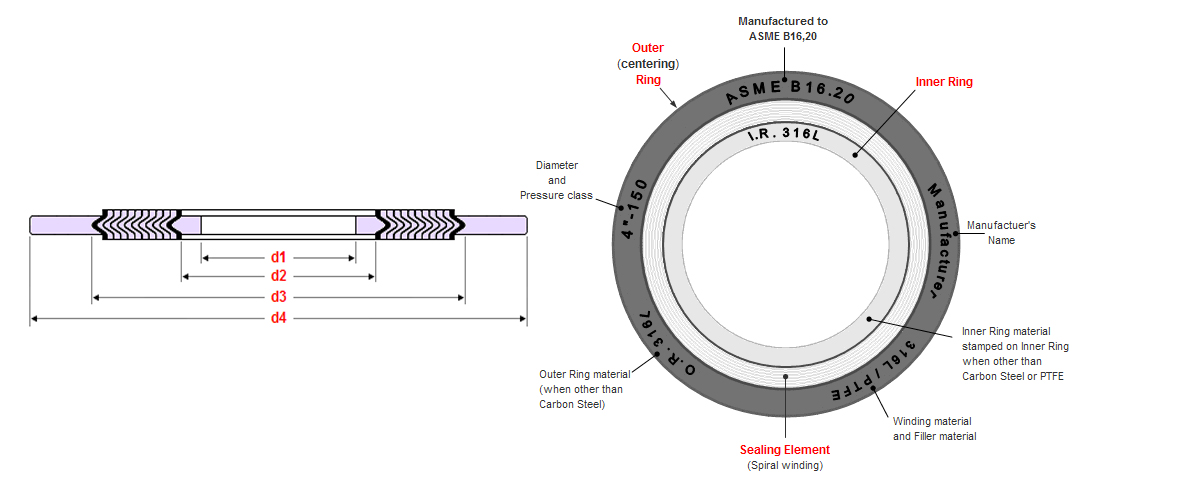
| Class 150 NPS 1/2-24 | ||||
| NPS | Inner Ring | Sealing Element | Outer Ring | |
| Inside (d1) Diameter | Inside (d2) Diameter | Outside (d3) Diameter | Outside (d4) Diameter | |
| 1/2 | 14.2 | 19.1 | 31.8 | 47.8 |
| 3/4 | 20.6 | 25.4 | 39.6 | 57.2 |
| 1 | 26.9 | 31.8 | 47.8 | 66.8 |
| 1.1/4 | 38.1 | 47.8 | 60.5 | 76.2 |
| 1.1/2 | 44.5 | 54.1 | 69.9 | 85.9 |
| 2 | 55.6 | 69.9 | 85.9 | 104.9 |
| 2.1/2 | 66.5 | 82.6 | 98.6 | 124 |
| 3 | 81 | 101.6 | 120.7 | 136.7 |
| 4 | 106.4 | 127 | 149.4 | 174.8 |
| 5 | 131.8 | 155.7 | 177.8 | 196.9 |
| 6 | 157.2 | 182.6 | 209.6 | 222.3 |
| 8 | 215.9 | 233.4 | 263.7 | 279.4 |
| 10 | 268.2 | 287.3 | 317.5 | 339.9 |
| 12 | 317.5 | 339.9 | 374.7 | 409.7 |
| 14 | 349.3 | 371.6 | 406.4 | 450.9 |
| 16 | 400.1 | 422.4 | 463.6 | 514.4 |
| 18 | 449.3 | 474.7 | 527.1 | 549.4 |
| 20 | 500.1 | 525.5 | 577.9 | 606.6 |
| 24 | 603.3 | 628.7 | 685.8 | 717.6 |
| NPS | Inside (d1) Diameter | Inside (d2) Diameter | Outside (d3) Diameter | Outside (d4) Diameter |
| Inner Ring | Sealing Element | Outer Ring | ||
Note:
- Dimensions are in millimeters unless otherwise indicated.
- Image shows a Spiral Wound gasket with Inner - and Outer ring.
- d1 = Inside diameter when Inner ring is used.
- d2 = Inside diameter sealing element when no Inner ring is used.
- d3 = Outside diameter of sealing element.
- d4 = Outside diameter of Outer ring.
- Thickness of inner and outer ring: 2.97 mm - 3.33 mm.
- Thickness sealing element: 4.45 mm.
- Tolerance Outside diameter for NPS 1/2 through NPS 8 is ± 0.8 mm; for NPS 10 trough NPS 24 tolerance is + 1.5 mm - 0.8 mm.
- ASME B16.20 does not covers class 400 flanges up to NPS 3 and class 900 flanges up to NPS 2.1/2.
- There are no class 400 flanges NPS 1/2 thru NPS 3 (use Class 600), class 900 flanges NPS 1/2 thru NPS 2.1/2 (use Class 1500), or class 2500 flanges NPS 14 or larger.
- The inner ring inside diameters shown for NPS 1.1/4 thru 2.1/2 in class 1500 and 2500 will produce inner ring widths of 0.12 inches, a practical minimum for production purposes.
- ASME B16.20 which covers spiral wound gaskets requires the use of solid metal inner rings in: Pressure Class 900, nominal pipe sizes 24 and larger, Pressure Class 1500 from nominal pipe sizes 12 and larger, Pressure Class 2500 from nominal pipe sizes 4 and larger and all PTFE filled gaskets.
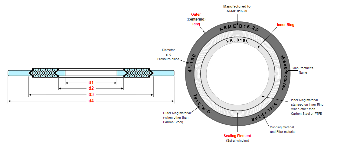
| Class 150 NPS 1/2-24 | ||||
| NPS | Inner Ring | Sealing Element | Outer Ring | |
| Inside (d1) Diameter | Inside (d2) Diameter | Outside (d3) Diameter | Outside (d4) Diameter | |
| 1/2 | 14.2 | 19.1 | 31.8 | 47.8 |
| 3/4 | 20.6 | 25.4 | 39.6 | 57.2 |
| 1 | 26.9 | 31.8 | 47.8 | 66.8 |
| 1.1/4 | 38.1 | 47.8 | 60.5 | 76.2 |
| 1.1/2 | 44.5 | 54.1 | 69.9 | 85.9 |
| 2 | 55.6 | 69.9 | 85.9 | 104.9 |
| 2.1/2 | 66.5 | 82.6 | 98.6 | 124 |
| 3 | 81 | 101.6 | 120.7 | 136.7 |
| 4 | 106.4 | 127 | 149.4 | 174.8 |
| 5 | 131.8 | 155.7 | 177.8 | 196.9 |
| 6 | 157.2 | 182.6 | 209.6 | 222.3 |
| 8 | 215.9 | 233.4 | 263.7 | 279.4 |
| 10 | 268.2 | 287.3 | 317.5 | 339.9 |
| 12 | 317.5 | 339.9 | 374.7 | 409.7 |
| 14 | 349.3 | 371.6 | 406.4 | 450.9 |
| 16 | 400.1 | 422.4 | 463.6 | 514.4 |
| 18 | 449.3 | 474.7 | 527.1 | 549.4 |
| 20 | 500.1 | 525.5 | 577.9 | 606.6 |
| 24 | 603.3 | 628.7 | 685.8 | 717.6 |
| NPS | Inside (d1) Diameter | Inside (d2) Diameter | Outside (d3) Diameter | Outside (d4) Diameter |
| Inner Ring | Sealing Element | Outer Ring | ||
Note:
- Dimensions are in millimeters unless otherwise indicated.
- Image shows a Spiral Wound gasket with Inner - and Outer ring.
- d1 = Inside diameter when Inner ring is used.
- d2 = Inside diameter sealing element when no Inner ring is used.
- d3 = Outside diameter of sealing element.
- d4 = Outside diameter of Outer ring.
- Thickness of inner and outer ring: 2.97 mm - 3.33 mm.
- Thickness sealing element: 4.45 mm.
- Tolerance Outside diameter for NPS 1/2 through NPS 8 is ± 0.8 mm; for NPS 10 trough NPS 24 tolerance is + 1.5 mm - 0.8 mm.
- ASME B16.20 does not covers class 400 flanges up to NPS 3 and class 900 flanges up to NPS 2.1/2.
- There are no class 400 flanges NPS 1/2 thru NPS 3 (use Class 600), class 900 flanges NPS 1/2 thru NPS 2.1/2 (use Class 1500), or class 2500 flanges NPS 14 or larger.
- The inner ring inside diameters shown for NPS 1.1/4 thru 2.1/2 in class 1500 and 2500 will produce inner ring widths of 0.12 inches, a practical minimum for production purposes.
- ASME B16.20 which covers spiral wound gaskets requires the use of solid metal inner rings in: Pressure Class 900, nominal pipe sizes 24 and larger, Pressure Class 1500 from nominal pipe sizes 12 and larger, Pressure Class 2500 from nominal pipe sizes 4 and larger and all PTFE filled gaskets.
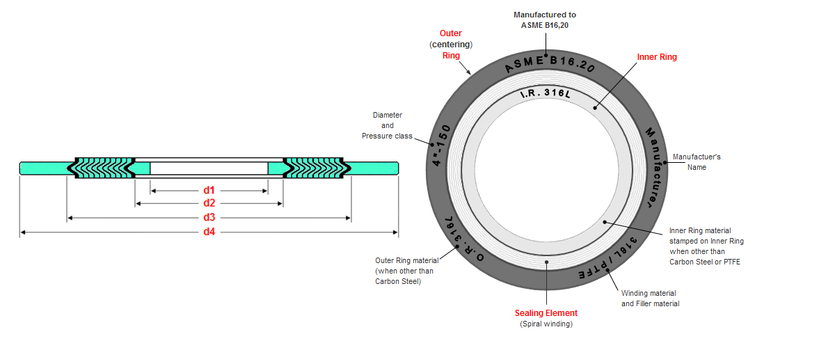
| Class 150 NPS 1/2-24 | ||||
| NPS | Inner Ring | Sealing Element | Outer Ring | |
| Inside (d1) Diameter | Inside (d2) Diameter | Outside (d3) Diameter | Outside (d4) Diameter | |
| 1/2 | 14.2 | 19.1 | 31.8 | 47.8 |
| 3/4 | 20.6 | 25.4 | 39.6 | 57.2 |
| 1 | 26.9 | 31.8 | 47.8 | 66.8 |
| 1.1/4 | 38.1 | 47.8 | 60.5 | 76.2 |
| 1.1/2 | 44.5 | 54.1 | 69.9 | 85.9 |
| 2 | 55.6 | 69.9 | 85.9 | 104.9 |
| 2.1/2 | 66.5 | 82.6 | 98.6 | 124 |
| 3 | 81 | 101.6 | 120.7 | 136.7 |
| 4 | 106.4 | 127 | 149.4 | 174.8 |
| 5 | 131.8 | 155.7 | 177.8 | 196.9 |
| 6 | 157.2 | 182.6 | 209.6 | 222.3 |
| 8 | 215.9 | 233.4 | 263.7 | 279.4 |
| 10 | 268.2 | 287.3 | 317.5 | 339.9 |
| 12 | 317.5 | 339.9 | 374.7 | 409.7 |
| 14 | 349.3 | 371.6 | 406.4 | 450.9 |
| 16 | 400.1 | 422.4 | 463.6 | 514.4 |
| 18 | 449.3 | 474.7 | 527.1 | 549.4 |
| 20 | 500.1 | 525.5 | 577.9 | 606.6 |
| 24 | 603.3 | 628.7 | 685.8 | 717.6 |
| NPS | Inside (d1) Diameter | Inside (d2) Diameter | Outside (d3) Diameter | Outside (d4) Diameter |
| Inner Ring | Sealing Element | Outer Ring | ||
Note:
- Dimensions are in millimeters unless otherwise indicated.
- Image shows a Spiral Wound gasket with Inner - and Outer ring.
- d1 = Inside diameter when Inner ring is used.
- d2 = Inside diameter sealing element when no Inner ring is used.
- d3 = Outside diameter of sealing element.
- d4 = Outside diameter of Outer ring.
- Thickness of inner and outer ring: 2.97 mm - 3.33 mm.
- Thickness sealing element: 4.45 mm.
- Tolerance Outside diameter for NPS 1/2 through NPS 8 is ± 0.8 mm; for NPS 10 trough NPS 24 tolerance is + 1.5 mm - 0.8 mm.
- ASME B16.20 does not covers class 400 flanges up to NPS 3 and class 900 flanges up to NPS 2.1/2.
- There are no class 400 flanges NPS 1/2 thru NPS 3 (use Class 600), class 900 flanges NPS 1/2 thru NPS 2.1/2 (use Class 1500), or class 2500 flanges NPS 14 or larger.
- The inner ring inside diameters shown for NPS 1.1/4 thru 2.1/2 in class 1500 and 2500 will produce inner ring widths of 0.12 inches, a practical minimum for production purposes.
- ASME B16.20 which covers spiral wound gaskets requires the use of solid metal inner rings in: Pressure Class 900, nominal pipe sizes 24 and larger, Pressure Class 1500 from nominal pipe sizes 12 and larger, Pressure Class 2500 from nominal pipe sizes 4 and larger and all PTFE filled gaskets.
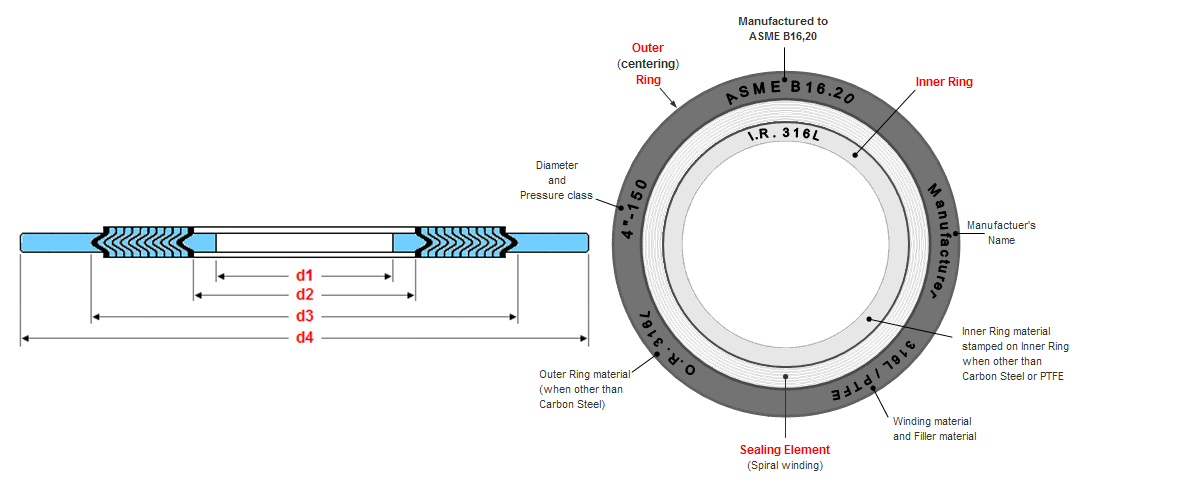
| Class 150 NPS 1/2-24 | ||||
| NPS | Inner Ring | Sealing Element | Outer Ring | |
| Inside (d1) Diameter | Inside (d2) Diameter | Outside (d3) Diameter | Outside (d4) Diameter | |
| 1/2 | 14.2 | 19.1 | 31.8 | 47.8 |
| 3/4 | 20.6 | 25.4 | 39.6 | 57.2 |
| 1 | 26.9 | 31.8 | 47.8 | 66.8 |
| 1.1/4 | 38.1 | 47.8 | 60.5 | 76.2 |
| 1.1/2 | 44.5 | 54.1 | 69.9 | 85.9 |
| 2 | 55.6 | 69.9 | 85.9 | 104.9 |
| 2.1/2 | 66.5 | 82.6 | 98.6 | 124 |
| 3 | 81 | 101.6 | 120.7 | 136.7 |
| 4 | 106.4 | 127 | 149.4 | 174.8 |
| 5 | 131.8 | 155.7 | 177.8 | 196.9 |
| 6 | 157.2 | 182.6 | 209.6 | 222.3 |
| 8 | 215.9 | 233.4 | 263.7 | 279.4 |
| 10 | 268.2 | 287.3 | 317.5 | 339.9 |
| 12 | 317.5 | 339.9 | 374.7 | 409.7 |
| 14 | 349.3 | 371.6 | 406.4 | 450.9 |
| 16 | 400.1 | 422.4 | 463.6 | 514.4 |
| 18 | 449.3 | 474.7 | 527.1 | 549.4 |
| 20 | 500.1 | 525.5 | 577.9 | 606.6 |
| 24 | 603.3 | 628.7 | 685.8 | 717.6 |
| NPS | Inside (d1) Diameter | Inside (d2) Diameter | Outside (d3) Diameter | Outside (d4) Diameter |
| Inner Ring | Sealing Element | Outer Ring | ||
Note:
- Dimensions are in millimeters unless otherwise indicated.
- Image shows a Spiral Wound gasket with Inner - and Outer ring.
- d1 = Inside diameter when Inner ring is used.
- d2 = Inside diameter sealing element when no Inner ring is used.
- d3 = Outside diameter of sealing element.
- d4 = Outside diameter of Outer ring.
- Thickness of inner and outer ring: 2.97 mm - 3.33 mm.
- Thickness sealing element: 4.45 mm.
- Tolerance Outside diameter for NPS 1/2 through NPS 8 is ± 0.8 mm; for NPS 10 trough NPS 24 tolerance is + 1.5 mm - 0.8 mm.
- ASME B16.20 does not covers class 400 flanges up to NPS 3 and class 900 flanges up to NPS 2.1/2.
- There are no class 400 flanges NPS 1/2 thru NPS 3 (use Class 600), class 900 flanges NPS 1/2 thru NPS 2.1/2 (use Class 1500), or class 2500 flanges NPS 14 or larger.
- The inner ring inside diameters shown for NPS 1.1/4 thru 2.1/2 in class 1500 and 2500 will produce inner ring widths of 0.12 inches, a practical minimum for production purposes.
- ASME B16.20 which covers spiral wound gaskets requires the use of solid metal inner rings in: Pressure Class 900, nominal pipe sizes 24 and larger, Pressure Class 1500 from nominal pipe sizes 12 and larger, Pressure Class 2500 from nominal pipe sizes 4 and larger and all PTFE filled gaskets.
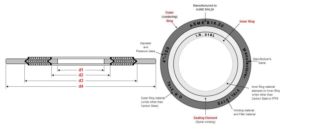
| Class 150 NPS 1/2-24 | ||||
| NPS | Inner Ring | Sealing Element | Outer Ring | |
| Inside (d1) Diameter | Inside (d2) Diameter | Outside (d3) Diameter | Outside (d4) Diameter | |
| 1/2 | 14.2 | 19.1 | 31.8 | 47.8 |
| 3/4 | 20.6 | 25.4 | 39.6 | 57.2 |
| 1 | 26.9 | 31.8 | 47.8 | 66.8 |
| 1.1/4 | 38.1 | 47.8 | 60.5 | 76.2 |
| 1.1/2 | 44.5 | 54.1 | 69.9 | 85.9 |
| 2 | 55.6 | 69.9 | 85.9 | 104.9 |
| 2.1/2 | 66.5 | 82.6 | 98.6 | 124 |
| 3 | 81 | 101.6 | 120.7 | 136.7 |
| 4 | 106.4 | 127 | 149.4 | 174.8 |
| 5 | 131.8 | 155.7 | 177.8 | 196.9 |
| 6 | 157.2 | 182.6 | 209.6 | 222.3 |
| 8 | 215.9 | 233.4 | 263.7 | 279.4 |
| 10 | 268.2 | 287.3 | 317.5 | 339.9 |
| 12 | 317.5 | 339.9 | 374.7 | 409.7 |
| 14 | 349.3 | 371.6 | 406.4 | 450.9 |
| 16 | 400.1 | 422.4 | 463.6 | 514.4 |
| 18 | 449.3 | 474.7 | 527.1 | 549.4 |
| 20 | 500.1 | 525.5 | 577.9 | 606.6 |
| 24 | 603.3 | 628.7 | 685.8 | 717.6 |
| NPS | Inside (d1) Diameter | Inside (d2) Diameter | Outside (d3) Diameter | Outside (d4) Diameter |
| Inner Ring | Sealing Element | Outer Ring | ||
Note:
- Dimensions are in millimeters unless otherwise indicated.
- Image shows a Spiral Wound gasket with Inner - and Outer ring.
- d1 = Inside diameter when Inner ring is used.
- d2 = Inside diameter sealing element when no Inner ring is used.
- d3 = Outside diameter of sealing element.
- d4 = Outside diameter of Outer ring.
- Thickness of inner and outer ring: 2.97 mm - 3.33 mm.
- Thickness sealing element: 4.45 mm.
- Tolerance Outside diameter for NPS 1/2 through NPS 8 is ± 0.8 mm; for NPS 10 trough NPS 24 tolerance is + 1.5 mm - 0.8 mm.
- ASME B16.20 does not covers class 400 flanges up to NPS 3 and class 900 flanges up to NPS 2.1/2.
- There are no class 400 flanges NPS 1/2 thru NPS 3 (use Class 600), class 900 flanges NPS 1/2 thru NPS 2.1/2 (use Class 1500), or class 2500 flanges NPS 14 or larger.
- The inner ring inside diameters shown for NPS 1.1/4 thru 2.1/2 in class 1500 and 2500 will produce inner ring widths of 0.12 inches, a practical minimum for production purposes.
- ASME B16.20 which covers spiral wound gaskets requires the use of solid metal inner rings in: Pressure Class 900, nominal pipe sizes 24 and larger, Pressure Class 1500 from nominal pipe sizes 12 and larger, Pressure Class 2500 from nominal pipe sizes 4 and larger and all PTFE filled gaskets.
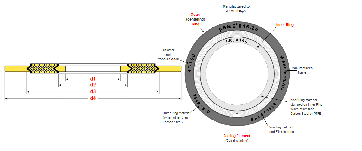
| Class 150 NPS 1/2-24 | ||||
| NPS | Inner Ring | Sealing Element | Outer Ring | |
| Inside (d1) Diameter | Inside (d2) Diameter | Outside (d3) Diameter | Outside (d4) Diameter | |
| 1/2 | 14.2 | 19.1 | 31.8 | 47.8 |
| 3/4 | 20.6 | 25.4 | 39.6 | 57.2 |
| 1 | 26.9 | 31.8 | 47.8 | 66.8 |
| 1.1/4 | 38.1 | 47.8 | 60.5 | 76.2 |
| 1.1/2 | 44.5 | 54.1 | 69.9 | 85.9 |
| 2 | 55.6 | 69.9 | 85.9 | 104.9 |
| 2.1/2 | 66.5 | 82.6 | 98.6 | 124 |
| 3 | 81 | 101.6 | 120.7 | 136.7 |
| 4 | 106.4 | 127 | 149.4 | 174.8 |
| 5 | 131.8 | 155.7 | 177.8 | 196.9 |
| 6 | 157.2 | 182.6 | 209.6 | 222.3 |
| 8 | 215.9 | 233.4 | 263.7 | 279.4 |
| 10 | 268.2 | 287.3 | 317.5 | 339.9 |
| 12 | 317.5 | 339.9 | 374.7 | 409.7 |
| 14 | 349.3 | 371.6 | 406.4 | 450.9 |
| 16 | 400.1 | 422.4 | 463.6 | 514.4 |
| 18 | 449.3 | 474.7 | 527.1 | 549.4 |
| 20 | 500.1 | 525.5 | 577.9 | 606.6 |
| 24 | 603.3 | 628.7 | 685.8 | 717.6 |
| NPS | Inside (d1) Diameter | Inside (d2) Diameter | Outside (d3) Diameter | Outside (d4) Diameter |
| Inner Ring | Sealing Element | Outer Ring | ||
Note:
- Dimensions are in millimeters unless otherwise indicated.
- Image shows a Spiral Wound gasket with Inner - and Outer ring.
- d1 = Inside diameter when Inner ring is used.
- d2 = Inside diameter sealing element when no Inner ring is used.
- d3 = Outside diameter of sealing element.
- d4 = Outside diameter of Outer ring.
- Thickness of inner and outer ring: 2.97 mm - 3.33 mm.
- Thickness sealing element: 4.45 mm.
- Tolerance Outside diameter for NPS 1/2 through NPS 8 is ± 0.8 mm; for NPS 10 trough NPS 24 tolerance is + 1.5 mm - 0.8 mm.
- ASME B16.20 does not covers class 400 flanges up to NPS 3 and class 900 flanges up to NPS 2.1/2.
- There are no class 400 flanges NPS 1/2 thru NPS 3 (use Class 600), class 900 flanges NPS 1/2 thru NPS 2.1/2 (use Class 1500), or class 2500 flanges NPS 14 or larger.
- The inner ring inside diameters shown for NPS 1.1/4 thru 2.1/2 in class 1500 and 2500 will produce inner ring widths of 0.12 inches, a practical minimum for production purposes.
- ASME B16.20 which covers spiral wound gaskets requires the use of solid metal inner rings in: Pressure Class 900, nominal pipe sizes 24 and larger, Pressure Class 1500 from nominal pipe sizes 12 and larger, Pressure Class 2500 from nominal pipe sizes 4 and larger and all PTFE filled gaskets.
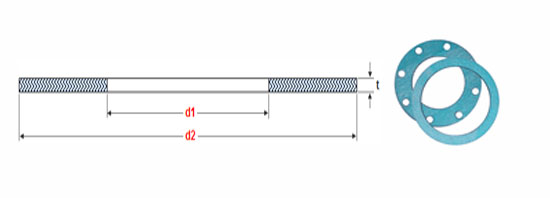
| Class 150 to 900 - NPS 1/2 to 24 | ||||||
| NPS | d1 | d2 | ||||
| Class 150 | Class 300 | Class 400 | Class 600 | Class 900 | ||
| 1/2 | 21 | 48 | 54 | 54 | 54 | 64 |
| 3/4 | 27 | 57 | 67 | 67 | 67 | 70 |
| 1 | 33 | 67 | 73 | 73 | 73 | 79 |
| 1.1/4 | 42 | 76 | 83 | 83 | 83 | 89 |
| 1.1/2 | 48 | 86 | 95 | 95 | 95 | 98 |
| 2 | 60 | 105 | 111 | 111 | 111 | 143 |
| 2.1/2 | 73 | 124 | 130 | 130 | 130.2 | 165 |
| 3 | 89 | 137 | 149 | 149 | 149 | 168 |
| 3.1/2 | 102 | 162 | 165 | 162 | 162 | ... |
| 4 | 114 | 175 | 181 | 178 | 194 | 206 |
| 5 | 141 | 197 | 216 | 213 | 241 | 248 |
| 6 | 168 | 222 | 251 | 248 | 267 | 289 |
| 8 | 219 | 279 | 308 | 305 | 321 | 359 |
| 10 | 273 | 340 | 362 | 359 | 400 | 435 |
| 12 | 324 | 410 | 422 | 419 | 457 | 498 |
| 14 | 356 | 451 | 486 | 483 | 492 | 521 |
| 16 | 406 | 514 | 540 | 537 | 565 | 575 |
| 18 | 457 | 549 | 597 | 594 | 613 | 638 |
| 20 | 508 | 606 | 654 | 648 | 683 | 699 |
| 24 | 610 | 718 | 775 | 768 | 791 | 838 |
| NPS | d1 | Class 150 | Class 300 | Class 400 | Class 600 | Class 900 |
| d2 | ||||||
Note:
- Dimensions are in millimeters unless otherwise indicated.
- d1 = Inside diameter.
- d2 = Outside diameter.
- Dimensional tolerances outside diameter NPS 12 and smaller: +0 / -1.5 mm.
- Dimensional tolerances outside diameter NPS 14 and larger: +0 / -3.0 mm.
- Dimensional tolerances inside diameter NPS 12 and smaller: ± 1.5 mm.
- Dimensional tolerances inside diameter NPS 14 and larger: ± 3.0 mm.
- Thickness (t) specified by customer.
| Class 150 - 400 | Class 600 - 2500 | ||||||||||||
| NPS | d1 | d2 | d3 | NPS | d1 | d2 | d3 | ||||||
| 150 | 300 | 400 | 600 | 900 | 1500 | 2500 | |||||||
| 1/2 | 23 | 33.3 | 44.4 | 50.8 | 50.8 | 1/2 | 23 | 33.3 | 50.8 | 60.3 | 60.3 | 66.7 | |
| 3/4 | 28.6 | 39.7 | 53.9 | 63.5 | 63.5 | 3/4 | 28.6 | 39.7 | 63.5 | 66.7 | 66.7 | 73 | |
| 1 | 36.5 | 47.6 | 63.5 | 69.8 | 69.8 | 1 | 36.5 | 47.6 | 69.8 | 76.2 | 76.2 | 82.5 | |
| 1.1/4 | 44.4 | 60.3 | 73 | 79.4 | 79.4 | 1.1/4 | 44.4 | 60.3 | 79.4 | 85.7 | 85.7 | 101.6 | |
| 1.1/2 | 52.4 | 69.8 | 82.5 | 92.1 | 92.1 | 1.1/2 | 52.4 | 69.8 | 92.1 | 95.2 | 95.2 | 114.3 | |
| 2 | 69.8 | 88.9 | 101.6 | 108 | 108 | 2 | 69.8 | 88.9 | 108 | 139.7 | 139.7 | 142.8 | |
| 2.1/2 | 82.5 | 101.6 | 120.6 | 127 | 127 | 2.1/2 | 82.5 | 101.6 | 127 | 161.9 | 161.9 | 165.1 | |
| 3 | 98.4 | 123.8 | 133.4 | 146.1 | 146.1 | 3 | 98.4 | 123.8 | 146.1 | 165.1 | 171.5 | 193.7 | |
| 3.1/2 | 111.1 | 136.5 | 158.8 | 161.9 | 158.7 | 3.1/2 | 111.1 | 136.5 | 158.7 | ... | ... | ... | |
| 4 | 123.8 | 154 | 171.5 | 177.8 | 174.6 | 4 | 123.8 | 154 | 190.5 | 203.2 | 206.4 | 231.7 | |
| 5 | 150.8 | 182.6 | 193.7 | 212.7 | 209.5 | 5 | 150.8 | 182.6 | 238.1 | 244.5 | 250.8 | 276.2 | |
| 6 | 177.8 | 212.7 | 219.1 | 247.7 | 244.5 | 6 | 177.8 | 212.7 | 263.5 | 285.8 | 279.4 | 314.3 | |
| 8 | 228.6 | 266.7 | 276.2 | 304.8 | 301.6 | 8 | 228.6 | 266.7 | 317.5 | 355.6 | 349.3 | 384.1 | |
| 10 | 282.6 | 320.7 | 336.5 | 358.8 | 355.6 | 10 | 282.6 | 320.7 | 369.9 | 431.8 | 431.8 | 473 | |
| 12 | 339.7 | 377.8 | 406.4 | 419.1 | 415.9 | 12 | 339.7 | 377.8 | 454 | 495.3 | 517.5 | 546.1 | |
| 14 | 371.5 | 409.6 | 447.7 | 482.6 | 479.4 | 14 | 371.5 | 409.6 | 488.9 | 517.5 | 574.7 | ... | |
| 16 | 422.3 | 466.7 | 511.2 | 536.6 | 533.4 | 16 | 422.3 | 466.7 | 561.9 | 571.5 | 638.1 | ... | |
| 18 | 479.4 | 530.2 | 546.1 | 593.7 | 590.5 | 18 | 479.4 | 530.2 | 609.6 | 635 | 701.7 | ... | |
| 20 | 530.2 | 581 | 603.2 | 650.9 | 644.5 | 20 | 530.2 | 581 | 679.5 | 695.3 | 752.4 | ... | |
| 24 | 631.8 | 682.6 | 714.4 | 771.5 | 765.2 | 24 | 631.8 | 682.6 | 787.4 | 835 | 898.5 | ... | |
| NPS | d1 | d2 | 150 | 300 | 400 | NPS | d1 | d2 | 600 | 900 | 1500 | 2500 | |
| d3 | d3 | ||||||||||||
Note:
- Dimensions are in millimeters unless otherwise indicated.
- Images shows Grooved Gaskets with Covering Layer and Centering Ring.
- d1 = Inside diameter.
- d2 = Outside diameter.
- d3 = Outside diameter of centering ring.
- Thickness (t) specified by customer.
| Class 150 - 400 | Class 600 - 2500 | |||||||||||
| NPS | d1 | d2 | NPS | d1 | d2 | |||||||
| 150 | 300 | 400 | 600 | 900 | 1500 | 2500 | ||||||
| 1/2 | 23.8 | 44.5 | 50.8 | 50.8 | 1/2 | 23.8 | 50.8 | 60.4 | 60.4 | 66.8 | ||
| 3/4 | 31.8 | 54 | 63.5 | 63.5 | 3/4 | 31.8 | 63.5 | 66.7 | 66.7 | 73.1 | ||
| 1 | 36.5 | 63.5 | 69.9 | 69.9 | 1 | 36.5 | 69.9 | 76.2 | 76.2 | 82.5 | ||
| 1.1/4 | 46 | 73 | 79.4 | 79.4 | 1.1/4 | 46 | 79.4 | 85.8 | 85.8 | 101.6 | ||
| 1.1/2 | 52.4 | 82.6 | 92.1 | 92.1 | 1.1/2 | 52.4 | 92.1 | 95.3 | 95.3 | 114.3 | ||
| 2 | 73.2 | 101.6 | 108 | 108 | 2 | 73.2 | 108 | 139.7 | 139.7 | 143 | ||
| 2.1/2 | 85.9 | 120.6 | 127 | 127 | 2.1/2 | 85.9 | 127 | 161.9 | 161.9 | 165.1 | ||
| 3 | 107.8 | 133.4 | 146.1 | 146.1 | 3 | 107.8 | 146.1 | 165.1 | 171.5 | 193.8 | ||
| 4 | 131.8 | 171.5 | 177.8 | 174.7 | 4 | 131.8 | 190.5 | 203.2 | 206.5 | 231.9 | ||
| 5 | 152.4 | 193.8 | 212.8 | 209.5 | 5 | 152.4 | 238.2 | 244.6 | 250.9 | 276.3 | ||
| 6 | 190.5 | 219.1 | 247.7 | 244.5 | 6 | 190.5 | 263.6 | 285.8 | 279.4 | 314.5 | ||
| 8 | 238.3 | 276.3 | 304.8 | 301.7 | 8 | 238.3 | 317.5 | 355.6 | 349.3 | 384.3 | ||
| 10 | 285.8 | 336.6 | 358.8 | 355.6 | 10 | 285.8 | 396.9 | 431.8 | 431.8 | 473.2 | ||
| 12 | 342.9 | 406.4 | 419.1 | 415.9 | 12 | 342.9 | 454.1 | 495.3 | 517.6 | 546.1 | ||
| 14 | 374.7 | 447.7 | 482.6 | 479.5 | 14 | 374.7 | 489 | 517.6 | 574.7 | ... | ||
| 16 | 425.5 | 511.2 | 536.6 | 533.4 | 16 | 425.5 | 562 | 571.5 | 638.2 | ... | ||
| 18 | 489 | 546.1 | 593.7 | 590.6 | 18 | 489 | 609.6 | 635 | 701.8 | ... | ||
| 20 | 533.4 | 603.3 | 650.9 | 644.5 | 20 | 533.4 | 679.5 | 695.5 | 752.5 | ... | ||
| 24 | 641.4 | 714.4 | 771.6 | 765.3 | 24 | 641.4 | 787.4 | 835.1 | 898.6 | ... | ||
| NPS | d1 | 150 | 300 | 400 | NPS | d1 | 600 | 900 | 1500 | 2500 | ||
| d2 | d2 | |||||||||||
Note:
- Dimensions are in millimeters unless otherwise indicated.
- d1 = Inside diameter.
- d2 = Outside diameter.
- Dimensional dimensional tolerances diameter up to NPS 24 = + 1.58 / - 0 mm for both diameters.
- Dimensional dimensional tolerances thickness (t) up to NPS 24 = + 0.80 / - 0 mm.
- Thickness (t) specified by customer.
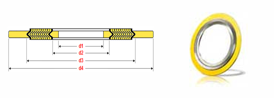
| DN | ID (d1) | ID (d2) | OD PN10- PN40 (d3) | OD PN64- PN250 (d3) | CENTRE RING OD (d4) | |||||||
| PN 10 | PN 16 | PN 25 | PN 40 | PN 63 | PN 100 | PN 160 | PN 250 | |||||
| 10 | 18 | 24 | 36 | 36 | 46 | 46 | 46 | 46 | 56 | 56 | 56 | 67 |
| 15 | 24 | 30 | 42 | 42 | 51 | 51 | 51 | 51 | 61 | 61 | 61 | 72 |
| 20 | 27 | 33 | 47 | 47 | 61 | 61 | 61 | 61 | 72 | 72 | ... | ... |
| 25 | 34 | 40 | 54 | 54 | 71 | 71 | 71 | 71 | 82 | 82 | 82 | 83 |
| 32 | 44 | 50 | 66 | 66 | 82 | 82 | 82 | 82 | 87 | 87 | ... | ... |
| 40 | 51 | 57 | 73 | 73 | 92 | 92 | 92 | 92 | 103 | 103 | 103 | 109 |
| 50 | 59 | 69 | 87 | 87 | 107 | 107 | 107 | 107 | 113 | 119 | 119 | 124 |
| 65 | 73 | 83 | 103 | 105 | 127 | 127 | 127 | 127 | 138 | 144 | 144 | 154 |
| 80 | 87 | 97 | 117 | 121 | 142 | 142 | 142 | 142 | 148 | 154 | 154 | 170 |
| 100 | 114 | 124 | 144 | 148 | 162 | 162 | 168 | 168 | 174 | 180 | 180 | 202 |
| 125 | 140 | 150 | 172 | 176 | 192 | 192 | 194 | 194 | 210 | 217 | 217 | 242 |
| 150 | 168 | 178 | 200 | 204 | 217 | 217 | 224 | 224 | 247 | 257 | 257 | 284 |
| 175 | 189 | 199 | 225 | 231 | 247 | 247 | 254 | 265 | 277 | 287 | 284 | 316 |
| 200 | 220 | 230 | 256 | 262 | 272 | 272 | 284 | 290 | 309 | 324 | 324 | 358 |
| 250 | 269 | 279 | 307 | 315 | 327 | 328 | 340 | 352 | 364 | 391 | 388 | 442 |
| 300 | 319 | 329 | 357 | 365 | 377 | 383 | 400 | 417 | 424 | 458 | 458 | 538 |
| 350 | 365 | 375 | 405 | 413 | 437 | 443 | 457 | 474 | 486 | 512 | ... | ... |
| 400 | 416 | 426 | 458 | 466 | 488 | 495 | 514 | 546 | 543 | 572 | ... | ... |
| 500 | 520 | 530 | 566 | 574 | 593 | 617 | 624 | 628 | 657 | 704 | ... | ... |
| 600 | 615 | 630 | 666 | 674 | 695 | 734 | 731 | 747 | 764 | 813 | ... | ... |
| 700 | 715 | 730 | 770 | 778 | 810 | 804 | 833 | 852 | 879 | ... | ... | ... |
| 800 | 815 | 830 | 874 | 882 | 917 | 911 | 942 | 974 | 988 | ... | ... | ... |
| 900 | 915 | 930 | 974 | 982 | 1017 | 1011 | 1042 | 1084 | 1108 | ... | ... | ... |
| 1000 | 1015 | 1030 | 1078 | 1086 | 1124 | 1128 | 1154 | 1194 | 1220 | ... | ... | ... |
| DN | ID (d1) | ID (d2) | OD PN10 - PN40 (d3) | OD PN64 - PN250 (d3) | PN 10 | PN 16 | PN 25 | PN 40 | PN 63 | PN 100 | PN 160 | PN 250 |
| CENTRE RING OD (d4) | ||||||||||||
ASME B16.5
| RING NO. | PITCH DIA P | WIDTH A | HEIGHT | WIDTH OCT. C | RADIUS OCT. R1 | NPS CLASS | |
| OVAL B | OCT. H | ||||||
| R-11 | 34.14 | 6.35 | 11.2 | 9.7 | 4.32 | 1.5 | 1/2 300-600 |
| R-12 | 39.7 | 7.95 | 14.2 | 12.7 | 5.23 | 1.5 | 1/2 900-1500 |
| R-13 | 42.88 | 7.95 | 14.2 | 12.7 | 5.23 | 1.5 | 3/4 300-600 1/2 2500 |
| R-14 | 44.45 | 7.95 | 14.2 | 12.7 | 5.23 | 1.5 | 3/4 900-1500 |
| R-15 | 47.63 | 7.95 | 14.2 | 12.7 | 5.23 | 1.5 | 1 150 |
| R-16 | 50.8 | 7.95 | 14.2 | 12.7 | 5.23 | 1.5 | 1 300-1500 3/4 2500 |
| R-17 | 57.15 | 7.95 | 14.2 | 12.7 | 5.23 | 1.5 | 1.1/4 150 |
| R-18 | 60.33 | 7.95 | 14.2 | 12.7 | 5.23 | 1.5 | 1.1/4 300-1500 1 2500 |
| R-19 | 65.1 | 7.95 | 14.2 | 12.7 | 5.23 | 1.5 | 1.1/2 150 |
| RING NO. | PITCH DIA P | WIDTH A | HEIGHT | WIDTH OCT. C | RADIUS OCT. R1 | NPS CLASS | |
| OVAL B | OCT. H | ||||||
| R-20 | 68.28 | 7.95 | 14.2 | 12.7 | 5.23 | 1.5 | 1.1/2 300-1500 |
| R-21 | 72.24 | 11.13 | 17.5 | 16 | 7.75 | 1.5 | 1.1/4 2500 |
| R-22 | 82.55 | 7.95 | 14.2 | 12.7 | 5.23 | 1.5 | 2 150 |
| R-23 | 82.55 | 11.13 | 17.5 | 16 | 7.75 | 1.5 | 2 300-600 1.1/2 2500 |
| R-24 | 95.25 | 11.13 | 17.5 | 16 | 7.75 | 1.5 | 2 900-1500 |
| R-25 | 101.6 | 7.95 | 14.2 | 12.7 | 5.23 | 1.5 | 2.1/2 150 |
| R-26 | 101.6 | 11.13 | 17.5 | 16 | 7.75 | 1.5 | 2.1/2 300-600 2 2500 |
| R-27 | 107.95 | 11.13 | 17.5 | 16 | 7.75 | 1.5 | 2.1/2 900-1500 |
| R-28 | 111.13 | 12.7 | 19.1 | 17.5 | 8.66 | 1.5 | 2.1/2 2500 |
| R-29 | 114.3 | 7.95 | 14.2 | 12.7 | 5.23 | 1.5 | 3 150 |
| RING NO. | PITCH DIA P | WIDTH A | HEIGHT | WIDTH OCT. C | RADIUS OCT. R1 | NPS CLASS | |
| OVAL B | OCT. H | ||||||
| R-30* | 117.48 | 11.13 | 17.5 | 16 | 7.75 | 1.5 | 3 300-600 |
| R-31 | 123.83 | 11.13 | 17.5 | 16 | 7.75 | 1.5 | 3 300-900 |
| R-32 | 127 | 12.7 | 19.1 | 17.5 | 8.66 | 1.5 | 3 2500 |
| R-33 | 131.78 | 7.95 | 14.2 | 12.7 | 5.23 | 1.5 | 3.1/2 150 |
| R-34 | 131.78 | 11.13 | 17.5 | 16 | 7.75 | 1.5 | 3.1/2 300-600 |
| R-35 | 136.53 | 11.13 | 17.5 | 16 | 7.75 | 1.5 | 3 1500 |
| R-36 | 149.23 | 7.95 | 14.2 | 12.7 | 5.23 | 1.5 | 4 150 |
| R-37 | 149.23 | 11.13 | 17.5 | 16 | 7.75 | 1.5 | 4 300-900 |
| R-38 | 157.18 | 15.88 | 22.4 | 20.6 | 10.49 | 1.5 | 4 2500 |
| R-39 | 161.93 | 11.13 | 17.5 | 16 | 7.75 | 1.5 | 4 1500 |
| RING NO. | PITCH DIA P | WIDTH A | HEIGHT | WIDTH OCT. C | RADIUS OCT. R1 | NPS CLASS | |
| OVAL B | OCT. H | ||||||
| R-40 | 171.45 | 7.95 | 14.2 | 12.7 | 5.23 | 1.5 | 5 150 |
| R-41 | 180.98 | 11.13 | 17.5 | 16 | 7.75 | 1.5 | 5 300-900 |
| R-42 | 190.5 | 19.05 | 25.4 | 23.9 | 12.32 | 1.5 | 5 2500 |
| R-43 | 193.68 | 7.95 | 14.2 | 12.7 | 5.23 | 1.5 | 6 150 |
| R-44 | 193.68 | 11.13 | 17.5 | 16 | 7.75 | 1.5 | 5 1500 |
| R-45 | 211.15 | 11.13 | 17.5 | 16 | 7.75 | 1.5 | 6 300-900 |
| R-46 | 211.15 | 12.7 | 19.1 | 17.5 | 8.66 | 1.5 | 6 1500 |
| R-47 | 228.6 | 19.05 | 25.4 | 23.9 | 12.32 | 1.5 | 6 2500 |
| R-48 | 247.65 | 7.95 | 14.2 | 12.7 | 5.23 | 1.5 | 8 150 |
| R-49 | 269.88 | 11.13 | 17.5 | 16 | 7.75 | 1.5 | 8 300-900 |
| RING NO. | PITCH DIA P | WIDTH A | HEIGHT | WIDTH OCT. C | RADIUS OCT. R1 | NPS CLASS | |
| OVAL B | OCT. H | ||||||
| R-50 | 269.88 | 15.88 | 22.4 | 20.6 | 10.49 | 1.5 | 8 1500 |
| R-51 | 279.4 | 22.23 | 28.7 | 26.9 | 14.81 | 1.5 | 8 2500 |
| R-52 | 304.8 | 7.95 | 14.2 | 12.7 | 5.23 | 1.5 | 10 150 |
| R-53 | 323.85 | 11.13 | 17.5 | 16 | 7.75 | 1.5 | 10 300-900 |
| R-54 | 323.85 | 15.88 | 22.4 | 20.6 | 10.49 | 1.5 | 10 1500 |
| R-55 | 342.9 | 28.58 | 36.6 | 35.1 | 19.81 | 2.3 | 10 2500 |
| R-56 | 381 | 7.95 | 14.2 | 12.7 | 5.23 | 1.5 | 12 150 |
| R-57 | 381 | 11.13 | 17.5 | 16 | 7.75 | 1.5 | 12 300-900 |
| R-58 | 381 | 22.23 | 28.7 | 26.9 | 14.81 | 1.5 | 12 1500 |
| R-59 | 396.88 | 7.95 | 14.2 | 12.7 | 5.23 | 1.5 | 14 150 |
| RING NO. | PITCH DIA P | WIDTH A | HEIGHT | WIDTH OCT. C | RADIUS OCT. R1 | NPS CLASS | |
| OVAL B | OCT. H | ||||||
| R-60 | 406.4 | 31.75 | 39.6 | 38.1 | 22.33 | 2.3 | 12 2500 |
| R-61 | 419.1 | 11.13 | 17.5 | 16 | 7.75 | 1.5 | 14 300-600 |
| R-62 | 419.1 | 15.88 | 22.4 | 20.6 | 10.49 | 1.5 | 14 900 |
| R-63 | 419.1 | 25.4 | 33.3 | 31.8 | 17.3 | 2.3 | 14 1500 |
| R-64 | 454.03 | 7.95 | 14.2 | 12.7 | 5.23 | 1.5 | 16 150 |
| R-65 | 469.9 | 11.13 | 17.5 | 16 | 7.75 | 1.5 | 16 300-600 |
| R-66 | 469.9 | 15.88 | 22.4 | 20.6 | 10.49 | 1.5 | 16 900 |
| R-67 | 469.9 | 28.58 | 36.6 | 35.1 | 19.81 | 2.3 | 16 1500 |
| R-68 | 517.53 | 7.95 | 14.2 | 12.7 | 5.23 | 1.5 | 18 150 |
| R-69 | 533.4 | 11.13 | 17.5 | 16 | 7.75 | 1.5 | 18 300-600 |
| RING NO. | PITCH DIA P | WIDTH A | HEIGHT | WIDTH OCT. C | RADIUS OCT. R1 | NPS CLASS | |
| OVAL B | OCT. H | ||||||
| R-70 | 533.4 | 19.05 | 25.4 | 23.9 | 12.32 | 1.5 | 18 900 |
| R-71 | 533.4 | 28.58 | 36.6 | 35.1 | 19.81 | 2.3 | 18 1500 |
| R-72 | 558.8 | 7.95 | 14.2 | 12.7 | 5.23 | 1.5 | 20 150 |
| R-73 | 584.2 | 12.7 | 19.1 | 17.5 | 8.66 | 1.5 | 20 300-600 |
| R-74 | 584.2 | 19.05 | 25.4 | 23.9 | 12.32 | 1.5 | 20 900 |
| R-75 | 584.2 | 31.75 | 39.6 | 38.1 | 22.33 | 2.3 | 20 1500 |
| R-76 | 673.1 | 7.95 | 14.2 | 12.7 | 5.23 | 1.5 | 24 150 |
| R-77 | 692.15 | 15.88 | 22.4 | 20.6 | 10.49 | 1.5 | 24 300-600 |
| R-78 | 692.15 | 25.4 | 33.3 | 31.8 | 17.3 | 2.3 | 24 900 |
| R-79 | 692.15 | 34.93 | 44.5 | 41.4 | 24.82 | 2.3 | 24 1500 |
| RING NO. | PITCH DIA P | WIDTH A | HEIGHT | WIDTH OCT. C | RADIUS OCT. R1 | NPS CLASS | |
| OVAL B | OCT. H | ||||||
ASME B16.47 SERIES A
| RING NO. | PITCH DIA P | WIDTH A | HEIGHT | WIDTH OCT. C | RADIUS OCT. R1 | NPS CLASS | |
| OVAL B | OCT. H | ||||||
| R-93 | 749.3 | 19.05 | ... | 23.9 | 12.32 | 1.5 | 26 300-600 |
| R-94 | 800.1 | 19.05 | ... | 23.9 | 12.32 | 1.5 | 28 300-600 |
| R-95 | 857.25 | 19.05 | ... | 23.9 | 12.32 | 1.5 | 30 300-600 |
| R-96 | 914.4 | 22.23 | ... | 26.9 | 14.81 | 1.5 | 32 300-600 |
| R-97 | 965.2 | 22.23 | ... | 26.9 | 14.81 | 1.5 | 34 300-600 |
| R-98 | 1022.35 | 22.23 | ... | 26.9 | 14.81 | 1.5 | 36 300-600 |
| R-100 | 749.3 | 28.58 | ... | 35.1 | 19.81 | 2.3 | 26 900 |
| R-101 | 800.1 | 31.75 | ... | 38.1 | 22.33 | 2.3 | 28 900 |
| R-102 | 857.25 | 31.75 | ... | 38.1 | 22.33 | 2.3 | 30 900 |
| R-103 | 914.4 | 31.75 | ... | 38.1 | 22.33 | 2.3 | 32 900 |
| R-104 | 965.2 | 34.93 | ... | 41.4 | 24.82 | 2.3 | 34 900 |
| R-105 | 1022.35 | 34.93 | ... | 41.4 | 24.82 | 2.3 | 36 900 |
| RING NO. | PITCH DIA P | WIDTH A | HEIGHT | WIDTH OCT. C | RADIUS OCT. R1 | NPS CLASS | |
| OVAL B | OCT. H | ||||||
Note:
All dimensions are in millimeters.
Tolerances:
- P = average pitch diameter of ring ±0.18
- A = width of ring ±0.20
- B & H = height of ring +1.3. -0.5
Variation in height throughout the entire circumference of any given ring shall not exceed 0.5 within these tolerances - C = width of flat on octagonal ring ±0.20
- R1 = radius in ring ±0.5
- 23 deg = angle ±0 deg 30 min
- R-30 = for lapped joint only
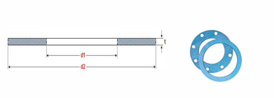
ASME B16.5
| Class 150 to 600 - NPS 26 to 60 - | |||||
| NPS | d1 | d2 | |||
| Class 150 | Class 300 | Class 400 | Class 600 | ||
| 26 | 660 | 775 | 835 | 832 | 867 |
| 28 | 711 | 832 | 899 | 892 | 914 |
| 30 | 762 | 883 | 953 | 946 | 972 |
| 32 | 813 | 940 | 1006 | 1003 | 1022 |
| 34 | 864 | 991 | 1057 | 1054 | 1073 |
| 36 | 914 | 1048 | 1118 | 1118 | 1130 |
| 38 | 965 | 1111 | 1054 | 1073 | 1105 |
| 40 | 1016 | 1162 | 1114 | 1127 | 1156 |
| 42 | 1067 | 1219 | 1165 | 1178 | 1219 |
| 44 | 1118 | 1276 | 1219 | 1232 | 1270 |
| 46 | 1168 | 1327 | 1273 | 1289 | 1327 |
| 48 | 1219 | 1384 | 1324 | 1346 | 1391 |
| 50 | 1270 | 1435 | 1378 | 1403 | 1448 |
| 52 | 1321 | 1492 | 1429 | 1454 | 1499 |
| 54 | 1372 | 1549 | 1492 | 1518 | 1556 |
| 56 | 1422 | 1607 | 1543 | 1568 | 1613 |
| 58 | 1473 | 1664 | 1594 | 1619 | 1664 |
| 60 | 1524 | 1715 | 1645 | 1683 | 1721 |
| NPS | d1 | Class 150 | Class 300 | Class 400 | Class 600 |
| d2 | |||||
Note:
- Dimensions are in millimeters unless otherwise indicated.
- d2 = Outside diameter.
- Dimensional tolerances outside diameter: +0 / -3.0 mm.
- Dimensional tolerances inside diameter: ± 3.0 mm.
- Thickness (t) specified by customer.
ASME B16.5
| Class 150 to 600 - NPS 26 to 60 - | |||||
| NPS | d1 | d2 | |||
| Class 150 | Class 300 | Class 400 | Class 600 | ||
| 26 | 660 | 725 | 772 | 746 | 765 |
| 28 | 711 | 776 | 826 | 800 | 819 |
| 30 | 762 | 827 | 886 | 857 | 879 |
| 32 | 813 | 881 | 940 | 911 | 933 |
| 34 | 864 | 935 | 994 | 962 | 997 |
| 36 | 914 | 987 | 1048 | 1022 | 1048 |
| 38 | 965 | 1045 | 1099 | ... | ... |
| 40 | 1016 | 1095 | 1149 | ... | ... |
| 42 | 1067 | 1146 | 1200 | ... | ... |
| 44 | 1118 | 1197 | 1251 | ... | ... |
| 46 | 1168 | 1256 | 1318 | ... | ... |
| 48 | 1219 | 1307 | 1368 | ... | ... |
| 50 | 1270 | 1357 | 1419 | ... | ... |
| 52 | 1321 | 1408 | 1470 | ... | ... |
| 54 | 1372 | 1464 | 1530 | ... | ... |
| 56 | 1422 | 1514 | 1594 | ... | ... |
| 58 | 1473 | 1580 | 1656 | ... | ... |
| 60 | 1524 | 1630 | 1705 | ... | ... |
| NPS | d1 | Class 150 | Class 300 | Class 400 | Class 600 |
| d2 | |||||
Note:
- Dimensions are in millimeters unless otherwise indicated.
- d1 = Inside diameter.
- d2 = Outside diameter.
- Dimensional tolerances outside diameter: +0 / -3.0 mm.
- Dimensional tolerances inside diameter: ± 3.0 mm.
- Thickness (t) specified by customer.

| Class 150 NPS 26-60 | ||||
| NPS | Inner Ring | Sealing Element | Outer Ring | |
| Inside (d1) Diameter | Inside (d2) Diameter | Outside (d3) Diameter | Outside (d4) Diameter | |
| 26 | 654.1 | 673.1 | 704.9 | 774.7 |
| 28 | 704.9 | 723.9 | 755.7 | 831.9 |
| 30 | 755.7 | 774.7 | 806.5 | 882.7 |
| 32 | 806.5 | 825.5 | 860.6 | 939.8 |
| 34 | 857.3 | 876.3 | 911.4 | 990.6 |
| 36 | 908.1 | 927.1 | 968.5 | 1047.8 |
| 38 | 958.9 | 977.9 | 1019.3 | 1111.3 |
| 40 | 1009.7 | 1028.7 | 1070.1 | 1162.1 |
| 42 | 1060.5 | 1079.5 | 1124 | 1219.2 |
| 44 | 1111.3 | 1130.3 | 1178.1 | 1276.4 |
| 46 | 1162.1 | 1181.1 | 1228.9 | 1327.2 |
| 48 | 1212.9 | 1231.9 | 1279.7 | 1384.3 |
| 50 | 1263.7 | 1282.7 | 1333.5 | 1435.1 |
| 52 | 1314.5 | 1333.5 | 1384.3 | 1492.3 |
| 54 | 1358.9 | 1384.3 | 1435.1 | 1549.4 |
| 56 | 1409.7 | 1435.1 | 1485.9 | 1606.6 |
| 58 | 1460.5 | 1485.9 | 1536.7 | 1663.7 |
| 60 | 1511.3 | 1536.7 | 1587.5 | 1714.5 |
| NPS | Inside (d1) Diameter | Inside (d2) Diameter | Outside (d3) Diameter | Outside (d4) Diameter |
| Inner Ring | Sealing Element | Outer Ring | ||

Note:
- Dimensions are in millimeters unless otherwise indicated.
- Image shows a Spiral Wound gasket with Inner - and Outer ring.
- d1 = Inside diameter when Inner ring is used.
- d2 = Inside diameter sealing element when no Inner ring is used.
- d3 = Outside diameter of sealing element.
- d4 = Outside diameter of Outer ring.
- The gasket thickness tolerance is ± 0.13 mm measured across the metallic portion of the gasket, not including the filler, which may protrude slightly beyond the metal.
- The gasket inside diameter tolerance for NPS 26 through NPS 34 is ± 0.8 mm, and the tolerance for NPS 36 through NPS 60 is ± 1.3 mm.
- The gasket outside diameter tolerance for NPS 26 through NPS 60 is ± 1.5 mm.
- The centering ring outside diameter tolerance is ± 0.8 mm.
- The inside diameter tolerance is ± 3.0 mm.
- Thickness of inner and outer ring: 2.97 mm - 3.33 mm.
- ASME B16.47 Series A flanges NPS 12 through NPS 24 have the same raised face dimensions as ASME B16.5 flanges.
- There are no Class 900 flanges NPS 50 and larger.

| Class 300 NPS 26-60 | ||||
| NPS | Inner Ring | Sealing Element | Outer Ring | |
| Inside (d1) Diameter | Inside (d2) Diameter | Outside (d3) Diameter | Outside (d4) Diameter | |
| 26 | 654.1 | 685.8 | 736.6 | 835.2 |
| 28 | 704.9 | 736.6 | 787.4 | 898.7 |
| 30 | 755.7 | 793.8 | 844.6 | 952.5 |
| 32 | 806.5 | 850.9 | 901.7 | 1006.6 |
| 34 | 857.3 | 901.7 | 952.5 | 1057.4 |
| 36 | 908.1 | 955.8 | 1006.6 | 1117.6 |
| 38 | 952.5 | 977.9 | 1016 | 1054.1 |
| 40 | 1003.3 | 1022.4 | 1070.1 | 1114.6 |
| 42 | 1054.1 | 1073.2 | 1120.9 | 1165.4 |
| 44 | 1104.9 | 1130.3 | 1181.1 | 1219.2 |
| 46 | 1152.7 | 1178.1 | 1228.9 | 1273.3 |
| 48 | 1209.8 | 1235.2 | 1286 | 1324.1 |
| 50 | 1244.6 | 1295.4 | 1346.2 | 1378 |
| 52 | 1320.8 | 1346.2 | 1397 | 1428.8 |
| 54 | 1352.6 | 1403.4 | 1454.2 | 1492.3 |
| 56 | 1403.4 | 1454.2 | 1505 | 1543.1 |
| 58 | 1447.8 | 1511.3 | 1562.1 | 1593.9 |
| 60 | 1524 | 1562.1 | 1612.9 | 1644.7 |
| NPS | Inside (d1) Diameter | Inside (d2) Diameter | Outside (d3) Diameter | Outside (d4) Diameter |
| Inner Ring | Sealing Element | Outer Ring | ||
Note:
- Dimensions are in millimeters unless otherwise indicated.
- Image shows a Spiral Wound gasket with Inner - and Outer ring.
- d1 = Inside diameter when Inner ring is used.
- d2 = Inside diameter sealing element when no Inner ring is used.
- d3 = Outside diameter of sealing element.
- d4 = Outside diameter of Outer ring.
- The gasket thickness tolerance is ± 0.13 mm measured across the metallic portion of the gasket, not including the filler, which may protrude slightly beyond the metal.
- The gasket inside diameter tolerance for NPS 26 through NPS 34 is ± 0.8 mm, and the tolerance for NPS 36 through NPS 60 is ± 1.3 mm.
- The gasket outside diameter tolerance for NPS 26 through NPS 60 is ± 1.5 mm.
- The centering ring outside diameter tolerance is ± 0.8 mm.
- The inside diameter tolerance is ± 3.0 mm.
- Thickness of inner and outer ring: 2.97 mm - 3.33 mm.
- ASME B16.47 Series A flanges NPS 12 through NPS 24 have the same raised face dimensions as ASME B16.5 flanges.
- There are no Class 900 flanges NPS 50 and larger.

| Class 400 NPS 26-60 | ||||
| NPS | Inner Ring | Sealing Element | Outer Ring | |
| Inside (d1) Diameter | Inside (d2) Diameter | Outside (d3) Diameter | Outside (d4) Diameter | |
| 26 | 660.4 | 685.8 | 736.6 | 891.9 |
| 28 | 711.2 | 736.6 | 787.4 | 892.3 |
| 30 | 755.7 | 793.8 | 844.6 | 946.2 |
| 32 | 812.8 | 850.9 | 901.7 | 1003.3 |
| 34 | 863.6 | 901.7 | 952.5 | 1054.1 |
| 36 | 917.7 | 955.8 | 1006.6 | 1117.6 |
| 38 | 952.5 | 971.6 | 1022.4 | 1073.2 |
| 40 | 1000.3 | 1025.7 | 1076.5 | 1127.3 |
| 42 | 1051.1 | 1076.5 | 1127.3 | 1178.1 |
| 44 | 1104.9 | 1130.3 | 1181.1 | 1231.9 |
| 46 | 1168.4 | 1193.8 | 1244.6 | 1289.1 |
| 48 | 1206.5 | 1244.6 | 1295.4 | 1346.2 |
| 50 | 1257.3 | 1295.4 | 1346.2 | 1403.4 |
| 52 | 1308.1 | 1346.2 | 1397 | 1454.2 |
| 54 | 1352.6 | 1403.4 | 1454.2 | 1517.7 |
| 56 | 1403.4 | 1454.2 | 1505 | 1568.5 |
| 58 | 1454.2 | 1505 | 1555.8 | 1619.3 |
| 60 | 1517.7 | 1568.5 | 1619.3 | 1682.8 |
| NPS | Inside (d1) Diameter | Inside (d2) Diameter | Outside (d3) Diameter | Outside (d4) Diameter |
| Inner Ring | Sealing Element | Outer Ring | ||
Note:
- Dimensions are in millimeters unless otherwise indicated.
- Image shows a Spiral Wound gasket with Inner - and Outer ring.
- d1 = Inside diameter when Inner ring is used.
- d2 = Inside diameter sealing element when no Inner ring is used.
- d3 = Outside diameter of sealing element.
- d4 = Outside diameter of Outer ring.
- The gasket thickness tolerance is ± 0.13 mm measured across the metallic portion of the gasket, not including the filler, which may protrude slightly beyond the metal.
- The gasket inside diameter tolerance for NPS 26 through NPS 34 is ± 0.8 mm, and the tolerance for NPS 36 through NPS 60 is ± 1.3 mm.
- The gasket outside diameter tolerance for NPS 26 through NPS 60 is ± 1.5 mm.
- The centering ring outside diameter tolerance is ± 0.8 mm.
- The inside diameter tolerance is ± 3.0 mm.
- Thickness of inner and outer ring: 2.97 mm - 3.33 mm.
- ASME B16.47 Series A flanges NPS 12 through NPS 24 have the same raised face dimensions as ASME B16.5 flanges.
- There are no Class 900 flanges NPS 50 and larger.

| Class 600 NPS 26-60 | ||||
| NPS | Inner Ring | Sealing Element | Outer Ring | |
| Inside (d1) Diameter | Inside (d2) Diameter | Outside (d3) Diameter | Outside (d4) Diameter | |
| 26 | 647.7 | 685.8 | 736.6 | 866.9 |
| 28 | 698.5 | 736.6 | 787.4 | 914.4 |
| 30 | 755.7 | 793.8 | 844.6 | 971.6 |
| 32 | 812.8 | 850.9 | 901.7 | 1022.4 |
| 34 | 863.6 | 901.7 | 952.5 | 1073.2 |
| 36 | 917.7 | 955.8 | 1006.6 | 1130.3 |
| 38 | 952.5 | 990.6 | 1041.4 | 1104.9 |
| 40 | 1009.7 | 1047.8 | 1098.6 | 1155.7 |
| 42 | 1066.8 | 1104.9 | 1155.7 | 1219.2 |
| 44 | 1111.3 | 1162.1 | 1212.9 | 1270 |
| 46 | 1162.1 | 1212.9 | 1263.7 | 1327.2 |
| 48 | 1219.2 | 1270 | 1320.8 | 1390.7 |
| 50 | 1270 | 1320.8 | 1371.6 | 1447.8 |
| 52 | 1320.8 | 1371.6 | 1422.4 | 1498.6 |
| 54 | 1378 | 1428.8 | 1479.6 | 1555.8 |
| 56 | 1428.8 | 1479.6 | 1530.4 | 1612.9 |
| 58 | 1473.2 | 1536.7 | 1587.5 | 1663.7 |
| 60 | 1530.4 | 1593.9 | 1644.7 | 1733.6 |
| NPS | Inside (d1) Diameter | Inside (d2) Diameter | Outside (d3) Diameter | Outside (d4) Diameter |
| Inner Ring | Sealing Element | Outer Ring | ||
Note:
- Dimensions are in millimeters unless otherwise indicated.
- Image shows a Spiral Wound gasket with Inner - and Outer ring.
- d1 = Inside diameter when Inner ring is used.
- d2 = Inside diameter sealing element when no Inner ring is used.
- d3 = Outside diameter of sealing element.
- d4 = Outside diameter of Outer ring.
- The gasket thickness tolerance is ± 0.13 mm measured across the metallic portion of the gasket, not including the filler, which may protrude slightly beyond the metal.
- The gasket inside diameter tolerance for NPS 26 through NPS 34 is ± 0.8 mm, and the tolerance for NPS 36 through NPS 60 is ± 1.3 mm.
- The gasket outside diameter tolerance for NPS 26 through NPS 60 is ± 1.5 mm.
- The centering ring outside diameter tolerance is ± 0.8 mm.
- The inside diameter tolerance is ± 3.0 mm.
- Thickness of inner and outer ring: 2.97 mm - 3.33 mm.
- ASME B16.47 Series A flanges NPS 12 through NPS 24 have the same raised face dimensions as ASME B16.5 flanges.
- There are no Class 900 flanges NPS 50 and larger.

| Class 900 NPS 26-48 | ||||
| NPS | Inner Ring | Sealing Element | Outer Ring | |
| Inside (d1) Diameter | Inside (d2) Diameter | Outside (d3) Diameter | Outside (d4) Diameter | |
| 26 | 660.4 | 685.8 | 736.6 | 882.7 |
| 28 | 711.2 | 736.6 | 787.4 | 946.2 |
| 30 | 768.4 | 793.8 | 844.6 | 1009.7 |
| 32 | 812.8 | 850.9 | 901.7 | 1073.2 |
| 34 | 863.6 | 901.7 | 952.5 | 1136.7 |
| 36 | 920.8 | 958.9 | 1009.7 | 1200.2 |
| 38 | 1009.7 | 1035.1 | 1085.9 | 1200.2 |
| 40 | 1060.5 | 1098.6 | 1149.4 | 1251 |
| 42 | 1111.3 | 1149.4 | 1200.2 | 1301.8 |
| 44 | 1155.7 | 1206.5 | 1257.3 | 1368.6 |
| 46 | 1219.2 | 1270 | 1320.8 | 1435.1 |
| 48 | 1270 | 1320.8 | 1371.6 | 1485.9 |
| NPS | Inside (d1) Diameter | Inside (d2) Diameter | Outside (d3) Diameter | Outside (d4) Diameter |
| Inner Ring | Sealing Element | Outer Ring | ||
Note:
- Dimensions are in millimeters unless otherwise indicated.
- Image shows a Spiral Wound gasket with Inner - and Outer ring.
- d1 = Inside diameter when Inner ring is used.
- d2 = Inside diameter sealing element when no Inner ring is used.
- d3 = Outside diameter of sealing element.
- d4 = Outside diameter of Outer ring.
- The gasket thickness tolerance is ± 0.13 mm measured across the metallic portion of the gasket, not including the filler, which may protrude slightly beyond the metal.
- The gasket inside diameter tolerance for NPS 26 through NPS 34 is ± 0.8 mm, and the tolerance for NPS 36 through NPS 60 is ± 1.3 mm.
- The gasket outside diameter tolerance for NPS 26 through NPS 60 is ± 1.5 mm.
- The centering ring outside diameter tolerance is ± 0.8 mm.
- The inside diameter tolerance is ± 3.0 mm.
- Thickness of inner and outer ring: 2.97 mm - 3.33 mm.
- ASME B16.47 Series A flanges NPS 12 through NPS 24 have the same raised face dimensions as ASME B16.5 flanges.
- There are no Class 900 flanges NPS 50 and larger.
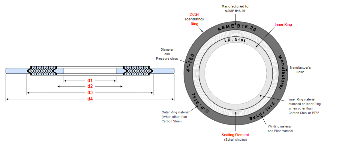
| Class 150 NPS 26-60 | ||||
| NPS | Inner Ring | Sealing Element | Outer Ring | |
| Inside (d1) Diameter | Inside (d2) Diameter | Outside (d3) Diameter | Outside (d4) Diameter | |
| 26 | 654.1 | 673.1 | 698.5 | 725.4 |
| 28 | 704.9 | 723.9 | 749.3 | 776.2 |
| 30 | 755.7 | 774.7 | 800.1 | 827 |
| 32 | 806.5 | 825.5 | 850.9 | 881.1 |
| 34 | 857.3 | 876.3 | 908.1 | 935 |
| 36 | 908.1 | 927.1 | 958.9 | 987.6 |
| 38 | 958.9 | 974.9 | 1009.7 | 1044.7 |
| 40 | 1009.7 | 1022.4 | 1063.8 | 1095.5 |
| 42 | 1060.5 | 1079.5 | 1114.6 | 1146.3 |
| 44 | 1111.3 | 1124 | 1165.4 | 1197.1 |
| 46 | 1162.1 | 1181.1 | 1224 | 1255.8 |
| 48 | 1212.9 | 1231.9 | 1270 | 1306.6 |
| 50 | 1263.7 | 1282.7 | 1325.6 | 1357.4 |
| 52 | 1314.5 | 1333.5 | 1376.4 | 1408.2 |
| 54 | 1365.3 | 1384.3 | 1422.4 | 1463.8 |
| 56 | 1422.4 | 1444.8 | 1478 | 1514.6 |
| 58 | 1478 | 1500.1 | 1528.8 | 1579.6 |
| 60 | 1535.2 | 1557.3 | 1586 | 1630.4 |
| NPS | Inside (d1) Diameter | Inside (d2) Diameter | Outside (d3) Diameter | Outside (d4) Diameter |
| Inner Ring | Sealing Element | Outer Ring | ||
Note:
- Dimensions are in millimeters unless otherwise indicated.
- Image shows a Spiral Wound gasket with Inner - and Outer ring.
- d1 = Inside diameter when Inner ring is used.
- d2 = Inside diameter sealing element when no Inner ring is used.
- d3 = Outside diameter of sealing element.
- d4 = Outside diameter of Outer ring.
- The gasket thickness tolerance is ± 0.13 mm measured across the metallic portion of the gasket, not including the filler, which may protrude slightly beyond the metal.
- The gasket inside diameter tolerance for NPS 26 through NPS 34 is ± 0.8 mm, and the tolerance for NPS 36 through NPS 60 is ± 1.3 mm.
- The gasket outside diameter tolerance for NPS 26 through NPS 60 is ± 1.5 mm.
- The centering ring outside diameter tolerance is ± 0.8 mm.
- The inside diameter tolerance is ± 3.0 mm.
- Thickness of inner and outer ring: 2.97 mm - 3.33 mm.
- There are no Class 900 flanges NPS 50 and larger.

| Class 300 NPS 26-60 | ||||
| NPS | Inner Ring | Sealing Element | Outer Ring | |
| Inside (d1) Diameter | Inside (d2) Diameter | Outside (d3) Diameter | Outside (d4) Diameter | |
| 26 | 654.1 | 673.1 | 711.2 | 771.7 |
| 28 | 704.9 | 723.9 | 762 | 825.5 |
| 30 | 755.7 | 774.7 | 812.8 | 886 |
| 32 | 806.5 | 825.5 | 863.6 | 939.8 |
| 34 | 857.3 | 876.3 | 914.4 | 993.9 |
| 36 | 908.1 | 927.1 | 965.2 | 1047.8 |
| 38 | 971.6 | 1009.7 | 1047.8 | 1098.6 |
| 40 | 1022.4 | 1060.5 | 1098.6 | 1149.4 |
| 42 | 1085.9 | 1111.3 | 1149.4 | 1200.2 |
| 44 | 1124 | 1162.1 | 1200.2 | 1251 |
| 46 | 1178.1 | 1216.2 | 1254.3 | 1317.8 |
| 48 | 1231.9 | 1263.7 | 1311.4 | 1368.6 |
| 50 | 1267 | 1317.8 | 1355.9 | 1419.4 |
| 52 | 1317.8 | 1368.6 | 1406.9 | 1470.2 |
| 54 | 1365.3 | 1403.4 | 1454.2 | 1530.4 |
| 56 | 1428.8 | 1479.6 | 1524 | 1593.9 |
| 58 | 1484.4 | 1535.2 | 1573.3 | 1655.8 |
| 60 | 1557.3 | 1589 | 1630.4 | 1706.6 |
| NPS | Inside (d1) Diameter | Inside (d2) Diameter | Outside (d3) Diameter | Outside (d4) Diameter |
| Inner Ring | Sealing Element | Outer Ring | ||
Note:
- Dimensions are in millimeters unless otherwise indicated.
- Image shows a Spiral Wound gasket with Inner - and Outer ring.
- d1 = Inside diameter when Inner ring is used.
- d2 = Inside diameter sealing element when no Inner ring is used.
- d3 = Outside diameter of sealing element.
- d4 = Outside diameter of Outer ring.
- The gasket thickness tolerance is ± 0.13 mm measured across the metallic portion of the gasket, not including the filler, which may protrude slightly beyond the metal.
- The gasket inside diameter tolerance for NPS 26 through NPS 34 is ± 0.8 mm, and the tolerance for NPS 36 through NPS 60 is ± 1.3 mm.
- The gasket outside diameter tolerance for NPS 26 through NPS 60 is ± 1.5 mm.
- The centering ring outside diameter tolerance is ± 0.8 mm.
- The inside diameter tolerance is ± 3.0 mm.
- Thickness of inner and outer ring: 2.97 mm - 3.33 mm.
- There are no Class 900 flanges NPS 50 and larger.

| Class 400 NPS 26-60 | ||||
| NPS | Inner Ring | Sealing Element | Outer Ring | |
| Inside (d1) Diameter | Inside (d2) Diameter | Outside (d3) Diameter | Outside (d4) Diameter | |
| 26 | 654.1 | 666.8 | 698.5 | 746.3 |
| 28 | 701.8 | 714.5 | 749.3 | 800.1 |
| 30 | 752.6 | 765.3 | 806.5 | 857.3 |
| 32 | 800.1 | 812.8 | 860.6 | 911.4 |
| 34 | 850.9 | 866.9 | 911.4 | 962.2 |
| 36 | 898.7 | 917.7 | 965.2 | 1022.4 |
| 38 | 952.5 | 971.6 | 1022.4 | 1073.2 |
| 40 | 1000.3 | 1025.7 | 1076.5 | 1127.3 |
| 42 | 1051.1 | 1076.5 | 1127.3 | 1178.1 |
| 44 | 1104.9 | 1130.3 | 1181.1 | 1231.9 |
| 46 | 1168.4 | 1193.8 | 1244.6 | 1289.1 |
| 48 | 1206.5 | 1244.6 | 1295.4 | 1346.2 |
| 50 | 1257.3 | 1295.4 | 1346.2 | 1403.4 |
| 52 | 1308.1 | 1346.2 | 1397 | 1454.2 |
| 54 | 1352.6 | 1403.4 | 1454.2 | 1517.7 |
| 56 | 1403.4 | 1454.2 | 1505 | 1568.5 |
| 58 | 1454.2 | 1505 | 1555.8 | 1619.3 |
| 60 | 1517.7 | 1568.5 | 1619.3 | 1682.8 |
| NPS | Inside (d1) Diameter | Inside (d2) Diameter | Outside (d3) Diameter | Outside (d4) Diameter |
| Inner Ring | Sealing Element | Outer Ring | ||
Note:
- Dimensions are in millimeters unless otherwise indicated.
- Image shows a Spiral Wound gasket with Inner - and Outer ring.
- d1 = Inside diameter when Inner ring is used.
- d2 = Inside diameter sealing element when no Inner ring is used.
- d3 = Outside diameter of sealing element.
- d4 = Outside diameter of Outer ring.
- The gasket thickness tolerance is ± 0.13 mm measured across the metallic portion of the gasket, not including the filler, which may protrude slightly beyond the metal.
- The gasket inside diameter tolerance for NPS 26 through NPS 34 is ± 0.8 mm, and the tolerance for NPS 36 through NPS 60 is ± 1.3 mm.
- The gasket outside diameter tolerance for NPS 26 through NPS 60 is ± 1.5 mm.
- The centering ring outside diameter tolerance is ± 0.8 mm.
- The inside diameter tolerance is ± 3.0 mm.
- Thickness of inner and outer ring: 2.97 mm - 3.33 mm.
- There are no Class 900 flanges NPS 50 and larger.

| Class 600 NPS 26-60 | ||||
| NPS | Inner Ring | Sealing Element | Outer Ring | |
| Inside (d1) Diameter | Inside (d2) Diameter | Outside (d3) Diameter | Outside (d4) Diameter | |
| 26 | 644.7 | 663.7 | 714.5 | 765.3 |
| 28 | 685.8 | 704.9 | 755.7 | 819.2 |
| 30 | 752.6 | 778 | 828.8 | 879.6 |
| 32 | 793.8 | 831.9 | 882.7 | 933.5 |
| 34 | 850.9 | 889 | 939.8 | 997 |
| 36 | 901.7 | 939.8 | 990.6 | 1047.8 |
| 38 | 952.5 | 990.6 | 1041.4 | 1104.9 |
| 40 | 1009.7 | 1047.8 | 1098.6 | 1155.7 |
| 42 | 1066.8 | 1104.9 | 1155.7 | 1219.2 |
| 44 | 1111.3 | 1162.1 | 1212.9 | 1270 |
| 46 | 1162.1 | 1212.9 | 1263.7 | 1327.2 |
| 48 | 1219.2 | 1270 | 1320.8 | 1390.7 |
| 50 | 1270 | 1320.8 | 1371.6 | 1447.8 |
| 52 | 1320.8 | 1371.6 | 1422.4 | 1498.6 |
| 54 | 1378 | 1428.8 | 1479.6 | 1555.8 |
| 56 | 1428.8 | 1479.6 | 1530.4 | 1612.9 |
| 58 | 1473.2 | 1536.7 | 1587.5 | 1663.7 |
| 60 | 1530.4 | 1593.9 | 1644.7 | 1733.6 |
| NPS | Inside (d1) Diameter | Inside (d2) Diameter | Outside (d3) Diameter | Outside (d4) Diameter |
| Inner Ring | Sealing Element | Outer Ring | ||
Note:
- Dimensions are in millimeters unless otherwise indicated.
- Image shows a Spiral Wound gasket with Inner - and Outer ring.
- d1 = Inside diameter when Inner ring is used.
- d2 = Inside diameter sealing element when no Inner ring is used.
- d3 = Outside diameter of sealing element.
- d4 = Outside diameter of Outer ring.
- The gasket thickness tolerance is ± 0.13 mm measured across the metallic portion of the gasket, not including the filler, which may protrude slightly beyond the metal.
- The gasket inside diameter tolerance for NPS 26 through NPS 34 is ± 0.8 mm, and the tolerance for NPS 36 through NPS 60 is ± 1.3 mm.
- The gasket outside diameter tolerance for NPS 26 through NPS 60 is ± 1.5 mm.
- The centering ring outside diameter tolerance is ± 0.8 mm.
- The inside diameter tolerance is ± 3.0 mm.
- Thickness of inner and outer ring: 2.97 mm - 3.33 mm.
- There are no Class 900 flanges NPS 50 and larger.
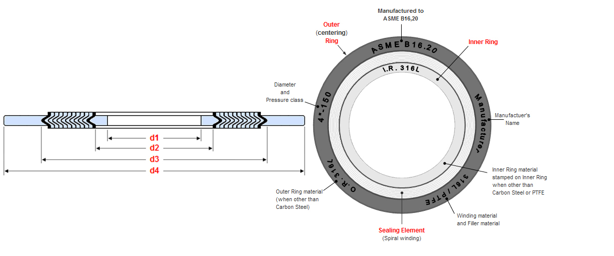
| Class 900 NPS 26-48 | ||||
| NPS | Inner Ring | Sealing Element | Outer Ring | |
| Inside (d1) Diameter | Inside (d2) Diameter | Outside (d3) Diameter | Outside (d4) Diameter | |
| 26 | 666.8 | 692.2 | 749.3 | 838.2 |
| 28 | 717.6 | 743 | 800.1 | 901.7 |
| 30 | 781.1 | 806.5 | 857.3 | 958.9 |
| 32 | 838.2 | 863.6 | 914.4 | 1016 |
| 34 | 895.4 | 920.8 | 971.6 | 1073.2 |
| 36 | 920.8 | 946.2 | 997 | 1124 |
| 38 | 1009.7 | 1035.1 | 1085.9 | 1200.2 |
| 40 | 1060.5 | 1098.6 | 1149.4 | 1251 |
| 42 | 1111.3 | 1149.4 | 1200.2 | 1301.8 |
| 44 | 1155.7 | 1206.5 | 1257.3 | 1368.6 |
| 46 | 1219.2 | 1270 | 1320.8 | 1435.1 |
| 48 | 1270 | 1320.8 | 1371.6 | 1485.9 |
| NPS | Inside (d1) Diameter | Inside (d2) Diameter | Outside (d3) Diameter | Outside (d4) Diameter |
| Inner Ring | Sealing Element | Outer Ring | ||
Note:
- Dimensions are in millimeters unless otherwise indicated.
- Image shows a Spiral Wound gasket with Inner - and Outer ring.
- d1 = Inside diameter when Inner ring is used.
- d2 = Inside diameter sealing element when no Inner ring is used.
- d3 = Outside diameter of sealing element.
- d4 = Outside diameter of Outer ring.
- The gasket thickness tolerance is ± 0.13 mm measured across the metallic portion of the gasket, not including the filler, which may protrude slightly beyond the metal.
- The gasket inside diameter tolerance for NPS 26 through NPS 34 is ± 0.8 mm, and the tolerance for NPS 36 through NPS 60 is ± 1.3 mm.
- The gasket outside diameter tolerance for NPS 26 through NPS 60 is ± 1.5 mm.
- The centering ring outside diameter tolerance is ± 0.8 mm.
- The inside diameter tolerance is ± 3.0 mm.
- Thickness of inner and outer ring: 2.97 mm - 3.33 mm.
- There are no Class 900 flanges NPS 50 and larger.
